Download
1 / 1
10 likes | 181 Views
Solar-Powered Phase Change Compressor. 1. 3. 2. 4. Addison Bender Jesse Diaz Emmanuel Ferdinand. Sponsor: Grant Peacock Advisors: Dr. Juan Ordoñez , John Dascomb. D. t. Energy Analysis. Project Need Design a refrigerant compressor that can be driven by solar-generated steam. δ.

E N D
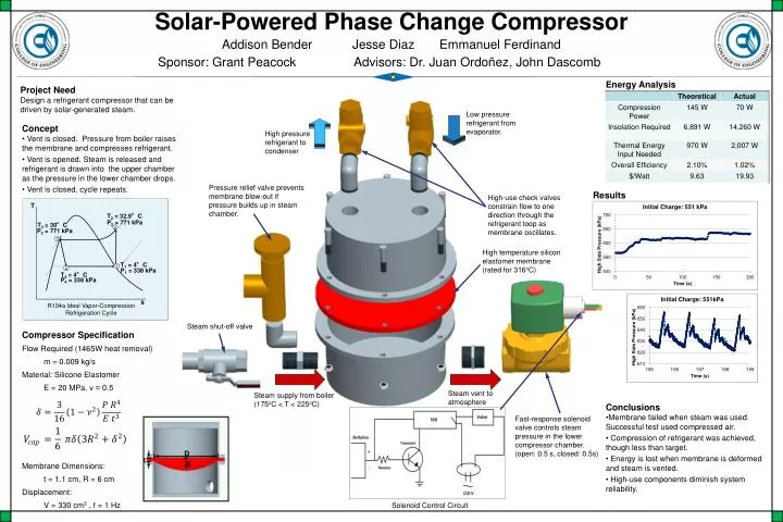
Solar-Powered Phase Change Compressor 1 3 2 4 Addison Bender Jesse Diaz Emmanuel Ferdinand Sponsor: Grant Peacock Advisors: Dr. Juan Ordoñez, John Dascomb D t Energy Analysis Project Need Design a refrigerant compressor that can be driven by solar-generated steam. δ Low pressure refrigerant from evaporator. • Concept • Vent is closed. Pressure from boiler raises the membrane and compresses refrigerant. • Vent is opened. Steam is released and refrigerant is drawn into the upper chamber as the pressure in the lower chamber drops. • Vent is closed, cycle repeats. High pressure refrigerant to condenser Pressure relief valve prevents membrane blow-out if pressure builds up in steam chamber. Results High-use check valves constrain flow to one direction through the refrigerant loop as membrane oscillates. T T2 = 32.9°C P2 = 771 kPa T3 = 30°C P3 = 771 kPa High temperature silicon elastomer membrane (rated for 316oC) T1 = 4°C P1 = 338 kPa T4 = 4°C P4 = 338 kPa s R134a Ideal Vapor-Compression Refrigeration Cycle Steam shut-off valve Compressor Specification Flow Required (1465W heat removal) m = 0.009 kg/s Material: Silicone Elastomer E = 20 MPa, ν = 0.5 Membrane Dimensions: t = 1.1 cm, R = 6 cm Displacement: V = 330 cm3 , f = 1 Hz Steam vent to atmosphere Steam supply from boiler (175oC < T < 225oC) • Conclusions • Membrane failed when steam was used. Successful test used compressed air. • Compression of refrigerant was achieved, though less than target. • Energy is lost when membrane is deformed and steam is vented. • High-use components diminish system reliability. Fast-response solenoid valve controls steam pressure in the lower compressor chamber. (open: 0.5 s, closed: 0.5s) Solenoid Control Circuit