Download
1 / 19
270 likes | 758 Views
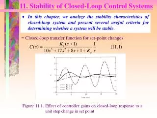
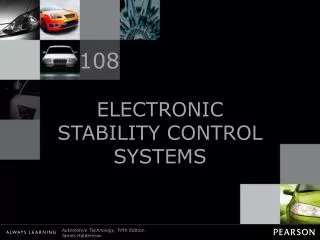
25. Electronic Stability Control Systems. Advanced Automotive Electricity and Electronics James D. Halderman. FIGURE 25.1 The electronic stability control (ESC) system applies individual wheel brakes to keep the vehicle under control of the driver.

E N D
25 Electronic StabilityControl Systems Advanced Automotive Electricity and Electronics James D. Halderman
FIGURE 25.1 The electronic stability control (ESC) system applies individual wheel brakes to keep the vehicle under control of the driver.
FIGURE 25.2 The sine with dwell test is designed to test the electronic stability control (ESC) system to determine if the system can keep the vehicle under control.
FIGURE 25.3 Using a simulator is the most cost-effective way for vehicle and aftermarket suspension manufacturers to check that the vehicle is able to perform within the FMVSS No. 126 standard for vehicle stability.
FIGURE 25.4 The hand-wheel position sensor is usually located at the base of the steering column.
FIGURE 25.5 Hand-wheel (steering wheel) position sensor schematic.
FIGURE 25.6 The VS sensor information is transmitted to the EBCM by Class 2 serial data.
FIGURE 25.7 A schematic showing the lateral acceleration sensor and EBCM.
FIGURE 25.8 A lateral acceleration sensor is usually located under the center console and can be easily checked by unbolting it and turn it on its side while monitoring the sensor value using a scan tool. When it is on its side the sensor value should read one G.
FIGURE 25.9 Yaw rate sensor showing the typical location and schematic.
FIGURE 25.10 Typical traction control system that uses wheel speed sensor information and the engine controller(PCM) to apply the brakes at lower speeds and also reduce engine power applied to the drive wheels.
FIGURE 25.11 Wheel speed sensor information is used to monitor if a drive wheel is starting to spin.
FIGURE 25.12 A traction control or low traction light on the dash is confusing to many drivers. When the lamp is onor flashing, it indicates that a low traction condition has been determined and the traction control system is working to restore traction. A flashing traction dash light does not indicate a fault.
FIGURE 25.13 The use of a factory scan tool is often needed to diagnose the ESC system.