Download
1 / 85
850 likes | 863 Views
RIGID BODY MOTION: TRANSLATION & ROTATION (Sections 16.1-16.3). Today’s Objectives : Students will be able to analyze the kinematics of a rigid body undergoing planar translation or rotation about a fixed axis. In-Class Activities : • Check homework, if any • Reading quiz

E N D
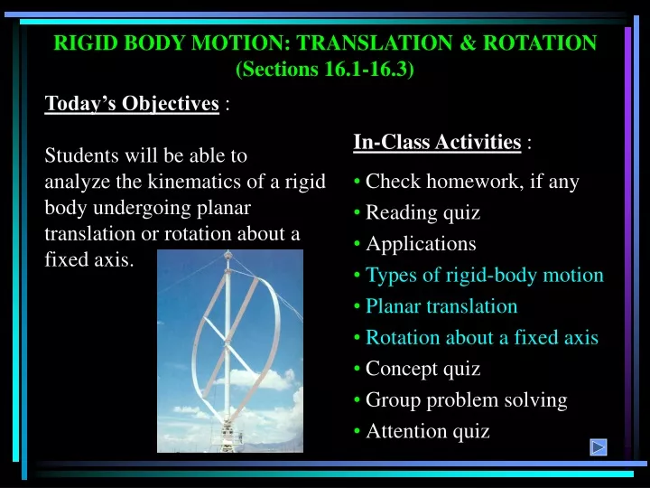
RIGID BODY MOTION: TRANSLATION & ROTATION (Sections 16.1-16.3) Today’s Objectives : Students will be able to analyze the kinematics of a rigid body undergoing planar translation or rotation about a fixed axis. In-Class Activities : • Check homework, if any • Reading quiz • Applications • Types of rigid-body motion • Planar translation • Rotation about a fixed axis • Concept quiz • Group problem solving • Attention quiz
APPLICATIONS Passengers on this amusement ride are subjected to curvilinear translation since the vehicle moves in a circular path but always remains upright. If the angular motion of the rotating arms is known, how can we determine the velocity and acceleration experienced by the passengers? Does each passenger feel the same acceleration?
APPLICATIONS (continued) Gears, pulleys and cams, which rotate about fixed axes, are often used in machinery to generate motion and transmit forces. The angular motion of these components must be understood to properly design the system. How can we relate the angular motions of contacting bodies that rotate about different fixed axes?
PLANAR KINEMATICS OF A RIGID BODY There are cases where an object cannot be treated as a particle. In these cases the size or shape of the body must be considered. Also, rotation of the body about its center of mass requires a different approach. For example, in the design of gears, cams, and links in machinery or mechanisms, rotation of the body is an important aspect in the analysis of motion. We will now start to study rigid body motion. The analysis will be limited to planar motion. A body is said to undergo planar motion when all parts of the body move along paths equidistant from a fixed plane.
PLANAR RIGID BODY MOTION There are three types of planar rigid body motion. Translation: Translation occurs if every line segment on the body remains parallel to its original direction during the motion. When all points move along straight lines, the motion is called rectilinear translation. When the paths of motion are curved lines, the motion is called curvilinear translation.
PLANAR RIGID BODY MOTION (continued) Rotation about a fixed axis. In this case, all the particles of the body, except those on the axis of rotation, move along circular paths in planes perpendicular to the axis of rotation. General plane motion. In this case, the body undergoes bothtranslation and rotation. Translation occurs within a plane and rotation occurs about an axis perpendicular to this plane.
E D B A C PLANAR RIGID BODY MOTION (continued) An example of bodies undergoing the three types of motion is shown in this mechanism. The wheel and crank (A and B) undergo rotation about a fixed axis. In this case, both axes of rotation are at the location of the pins and perpendicular to the plane of the figure. The piston (C) undergoes rectilinear translation since it is constrained to slide in a straight line. The connecting rod (D) undergoes curvilinear translation, since it will remain horizontal as it moves along a circular path. The connecting rod (E) undergoes general plane motion, as it will both translate and rotate.
RIGID-BODY MOTION: TRANSLATION The positions of two points A and B on a translating body can be related by rB = rA + rB/A where rA& rB are the absolute position vectors defined from the fixed x-y coordinate system, and rB/A is the relative-position vector between B and A. The velocity at B is vB= vA+ drB/A/dt . Now drB/A/dt= 0 since rB/A is constant. So, vB= vA, and by following similar logic, aB= aA. Note, all points in a rigid body subjected to translation move with the same velocity and acceleration.
Angular velocity, , is obtained by taking the time derivative of angular displacement: = d/dt (rad/s) + Similarly, angular acceleration is = d2/dt2 = d/dt or = (d/d) + rad/s2 RIGID-BODY MOTION: ROTATION ABOUT A FIXED AXIS When a body rotates about a fixed axis, any point P in the body travels along a circular path. The angular position of P is defined by q. The change in angular position, d, is called the angular displacement, with units of either radians or revolutions. They are related by 1 revolution = 2 radians
RIGID-BODY MOTION: ROTATION ABOUT A FIXED AXIS (continued) If the angular acceleration of the body is constant, a = aC, the equations for angular velocity and acceleration can be integrated to yield the set of algebraic equations below. w = wO + aCt q = qO + wOt + 0.5aCt2 w2 = (wO)2 + 2aC (q – qO) qO and wO are the initial values of the body’s angular position and angular velocity. Note these equations are very similar to the constant acceleration relations developed for the rectilinear motion of a particle.
The magnitude of the velocity of P is equal to wr (the text provides the derivation). The velocity’s direction is tangent to the circular path of P. RIGID-BODY ROTATION: VELOCITY OF POINT P In the vector formulation, the magnitude and direction of v can be determined from the cross product of w and rp. Here rp is a vector from any point on the axis of rotation to P. v = w x rp = w x r The direction of v is determined by the right-hand rule.
RIGID-BODY ROTATION: ACCELERATION OF POINT P The acceleration of P is expressed in terms of its normal (an) and tangential (at) components. In scalar form, these are at = a r and an = w2 r. The tangential component, at, represents the time rate of change in the velocity's magnitude. It is directed tangent to the path of motion. The normal component, an, represents the time rate of change in the velocity’s direction. It is directed toward the center of the circular path.
The magnitude of the acceleration vector is a = (at)2 + (an)2 RIGID-BODY ROTATION: ACCELERATION OF POINT P (continued) Using the vector formulation, the acceleration of P can also be defined by differentiating the velocity. a = dv/dt = dw/dt x rP + w x drP/dt = a x rP + w x (w x rP) It can be shown that this equation reduces to a = a x r – w2r = at + an
• To determine the motion of a point, the scalar equations v = w r, at = a r, an = w2r , and a = (at)2 + (an)2 can be used. ROTATION ABOUT A FIXED AXIS: PROCEDURE • Establish a sign convention along the axis of rotation. • If a relationship is known between any two of the variables (a, w, q, or t), the other variables can be determined from the equations: w = dq/dt a = dw/dt a dq = w dw • If a is constant, use the equations for constant angular acceleration. • Alternatively, the vector form of the equations can be used (with i, j, k components). v = w x rP = w x r a= at + an = a x rP + w x (w x rP) = a x r – w2r
EXAMPLE Given: The motor M begins rotating at w = 4(1 – e-t) rad/s, where t is in seconds. The radii of the motor, fan pulleys, and fan blades are 1 in, 4 in, and 16 in, respectively. Find: The magnitudes of the velocity and acceleration at point P on the fan blade when t = 0.5 s. Plan: 1) Determine the angular velocity and acceleration of the motor using kinematics of angular motion. 2) Assuming the belt does not slip, the angular velocity and acceleration of the fan are related to the motor's values by the belt. 3) The magnitudes of the velocity and acceleration of point P can be determined from the scalar equations of motion for a point on a rotating body.
1) Since the angular velocity is given as a function of time, wm = 4(1 – e-t), the angular acceleration can be found by differentiation. am = dwm/dt = 4e-t rad/s2 EXAMPLE (continued) Solution: When t = 0.5 s, wm = 4(1 – e-0.5) = 1.5739 rad/s, am = 4e-0.5 = 2.4261 rad/s2 2) Since the belt does not slip (and is assumed inextensible), it must have the same speed and tangential component of acceleration at all points. Thus the pulleys must have the same speed and tangential acceleration at their contact points with the belt. Therefore, the angular velocities of the motor (wm) and fan (wf) are related as v = wm rm = wf rf => (1.5739)(1) = wf(4) => wf = 0.3935 rad/s
The magnitude of the acceleration of P can be determined by aP = (an)2 + (at)2 = (2.477)2 + (9.704)2 = 10.0 in/s2 EXAMPLE (continued) 3) Similarly, the tangential accelerations are related as at = am rm = af rf => (2.4261)(1) = af(4) => af = 0.6065 rad/s2 4) The speed of point P on the the fan, at a radius of 16 in, is now determined as vP = wfrP = (0.3935)(16) = 6.30 in/s The normal and tangential components of acceleration of point P are calculated as an = (wf)2 rP = (0.3935)2 (16) = 2.477 in/s2 at = af rP = (0.6065) (16) = 9.704 in/s2
GROUP PROBLEM SOLVING Given: Starting from rest when s = 0, pulley A (rA = 50 mm) is given a constant angular acceleration, aA = 6 rad/s2. Pulley C (rC = 150 mm) has an inner hub D (rD = 75 mm) which is fixed to C and turns with it. Find: The speed of block B when it has risen s = 6 m. Plan: 1) The angular acceleration of pulley C (and hub D) can be related to aA if it is assumed the belt is inextensible and does not slip. 2) The acceleration of block B can be determined by using the equations for motion of a point on a rotating body. 3) The velocity of B can be found by using the constant acceleration equations.
aB = (at)D = aDrD = (2)(0.075) = 0.15 m/s2 GROUP PROBLEM SOLVING (continued) Solution: 1) Assuming the belt is inextensible and does not slip, it will have the same speed and tangential component of acceleration as it passes over the two pulleys (A and C). Thus, at = aArA = aCrC => (6)(50) = aC(150) => aC = 2 rad/s2 Since C and D turn together, aD = aC = 2 rad/s2 2) Assuming the cord attached to block B is inextensible and does not slip, the speed and acceleration of B will be the same as the speed and tangential component of acceleration along the outer rim of hub D:
(vB)2 = (vo)2 + 2aB(s – so) + (vB)2 = 0 + 2(0.15)(6 – 0) vB = 1.34 m/s GROUP PROBLEM SOLVING (continued) 3) Since aA is constant, aD and aB will be constant. The constant acceleration equation for rectilinear motion can be used to determine the speed of block B when s = 6 m (so = vo = 0):
End of the Lecture Let Learning Continue
ABSOLUTE MOTION ANALYSIS (Section 16.4) Today’s Objective: Students will be able to determine the velocity and acceleration of a rigid body undergoing general plane motion using an absolute motion analysis. In-Class Activities: • Check homework, if any • Reading quiz • Applications • General Plane Motion • Concept quiz • Group problem solving • Attention quiz
APPLICATIONS The position of the piston, x, can be defined as a function of the angular position of the crank, q. By differentiating x with respect to time, the velocity of the piston can be related to the angular velocity, w, of the crank. The stroke of the piston is defined as the total distance moved by the piston as the crank angle varies from 0 to 180°. How does the length of crank AB affect the stroke?
APPLICATIONS (continued) The rolling of a cylinder is an example of general plane motion. During this motion, the cylinder rotates clockwise while it translates to the right. The position of the center, G, is related to the angular position, q, by sG = r q if the cylinder rolls without slipping. Can you relate the translational velocity of G and the angular velocity of the cylinder?
PROCEDURE FOR ANALYSIS The absolute motion analysis method (also called the parametric method) relates the position of a point, P, on a rigid body undergoing rectilinear motion to the angular position, q (parameter), of a line contained in the body. (Often this line is a link in a machine.) Once a relationship in the form of sP = f(q) is established, the velocity and acceleration of point P are obtained in terms of the angular velocity, w, and angular acceleration, a, of the rigid body by taking the first and second time derivatives of the position function. Usually the chain rule must be used when taking the derivatives of the position coordinate equation.
EXAMPLE 1 Given: Two slider blocks are connected by a rod of length 2 m. Also, vA = 8 m/s and aA = 0. Find: Angular velocity, w, and angular acceleration, a, of the rod when q = 60°. Plan: Choose a fixed reference point and define the position of the slider A in terms of the parameter q. Notice from the position vector of A, positive angular position q is measured clockwise.
reference q A sA EXAMPLE 1 (continued) Solution: By geometry, sA = 2 cos q By differentiating with respect to time, vA = -2 w sin q Using q = 60° and vA = 8 m/s and solving for w: w = 8/(-2 sin 60°) = - 4.62 rad/s (The negative sign means the rod rotates counterclockwise as point A goes to the right.) Differentiating vA and solving for a, aA = -2a sin q – 2w2 cos q = 0 a = - w2/tan q = -12.32 rad/s2
Solution: xP = 0.2 cos q + (0.75)2 – (0.2 sin q)2 vP = -0.2w sin q + (0.5)[(0.75)2 – (0.2sin q)2]-0.5(-2)(0.2sin q)(0.2cos q)w vP = -0.2w sin q – [0.5(0.2)2sin2qw] / (0.75)2 – (0.2 sin q)2 At q = 30°, w = 150 rad/s and vP = -18.5 ft/s = 18.5 ft/s EXAMPLE 2 Given: Crank AB rotates at a constant velocity of w = 150 rad/s Find: Velocity of P when q = 30° Plan: Define x as a function of q and differentiate with respect to time.
GROUP PROBLEM SOLVING Given: The w and a of the disk and the dimensions as shown. Find: The velocity and acceleration of cylinder B in terms of q. Plan: Relate s, the length of cable between A and C, to the angular position, q. The velocity of cylinder B is equal to the time rate of change of s.
Law of cosines: s = (3)2 + (5)2 – 2(3)(5) cos q vB = (0.5)[34 – 30 cosq]-0.5(30 sinq)w vB = [15 sin q w]/ 34 – 30 cos q + (15w2 cosq 15a sinq) (-0.5)(15w sinq)(30w sinq) = + aB 34 - 30cosq (34 - 30cosq)3/2 + 15(w2cosq a sinq) 225w2sin2q = - aB - (34 - 30 cosq)0.5 (34 30 cosq)3/2 GROUP PROBLEM SOLVING (continued) Solution:
End of the Lecture Let Learning Continue
RELATIVE MOTION ANALYSIS: VELOCITY (Section 16.5) • Today’s Objectives: • Students will be able to: • Describe the velocity of a rigid body in terms of translation and rotation components. • Perform a relative-motion velocity analysis of a point on the body. In-Class Activities: • Check homework, if any • Reading quiz • Applications • Translation and rotation components of velocity • Relative velocity analysis • Concept quiz • Group problem solving • Attention quiz
APPLICATIONS As the slider block A moves horizontally to the left with vA, it causes the link CB to rotate counterclockwise. Thus vB is directed tangent to its circular path. Which link is undergoing general plane motion? How can its angular velocity, , be found?
APPLICATIONS (continued) Planetary gear systems are used in many automobile automatic transmissions. By locking or releasing different gears, this system can operate the car at different speeds. How can we relate the angular velocities of the various gears in the system?
= Disp. due to translation drB=drA+drB/A Disp. due to rotation Disp. due to translation and rotation RELATIVE MOTION ANALYSIS: DISPLACEMENT When a body is subjected to general plane motion, it undergoes a combination of translation and rotation. Point A is called the base point in this analysis. It generally has a known motion. The x’-y’ frame translates with the body, but does not rotate. The displacement of point B can be written:
= + RELATIVE MOTION ANALYSIS: VELOCITY The velocity at B is given as :(drB/dt) = (drA/dt) + (drB/A/dt)or vB=vA+vB/A Since the body is taken as rotating about A, vB/A = drB/A/dt = w x rB/A Here w will only have a k component since the axis of rotation is perpendicular to the plane of translation.
RELATIVE MOTION ANALYSIS: VELOCITY (continued) vB = vA + w x rB/A When using the relative velocity equation, points A and B should generally be points on the body with a known motion. Often these points are pin connections in linkages. Here both points A and B have circular motion since the disk and link BC move in circular paths. The directions of vA and vB are known since they are always tangent to the circular path of motion.
RELATIVE MOTION ANALYSIS: VELOCITY (continued) vB = vA + w x rB/A When a wheel rolls without slipping, point A is often selected to be at the point of contact with the ground. Since there is no slipping, point A has zero velocity. Furthermore, point B at the center of the wheel moves along a horizontal path. Thus, vB has a known direction, e.g., parallel to the surface.
PROCEDURE FOR ANALYSIS The relative velocity equation can be applied using either a Cartesian vector analysis or by writing scalar x and y component equations directly. Scalar Analysis: 1. Establish the fixed x-y coordinate directions and draw a kinematic diagram for the body. Then establish the magnitude and direction of the relative velocity vector vB/A. 2. Write the equation vB = vA + vB/A and by using the kinematic diagram, underneath each term represent the vectors graphically by showing their magnitudes and directions. 3. Write the scalar equations from the x and y components of these graphical representations of the vectors. Solve for the unknowns.
PROCEDURE FOR ANALYSIS (continued) Vector Analysis: 1. Establish the fixed x-y coordinate directions and draw the kinematic diagram of the body, showing the vectors vA, vB, rB/A and w. If the magnitudes are unknown, the sense of direction may be assumed. 2. Express the vectors in Cartesian vector form and substitute into vB = vA + w x rB/A. Evaluate the cross product and equate respective i and j components to obtain two scalar equations. 3. If the solution yields a negative answer, the sense of direction of the vector is opposite to that assumed.
EXAMPLE 1 Given: Block A is moving down at 2 m/s. Find: The velocity of B at the instant = 45. Plan: 1. Establish the fixed x-y directions and draw a kinematic diagram. 2. Express each of the velocity vectors in terms of their i, j, k components and solve vB = vA + w x rB/A.
EXAMPLE 1 (continued) Solution: vB = vA + wAB x rB/A vBi= -2 j + (wkx (0.2 sin 45 i - 0.2 cos 45 j )) vBi= -2 j + 0.2 w sin 45 j + 0.2 w cos 45 i Equating the i and j components gives: vB = 0.2 w cos 45 0 = -2 + 0.2 w sin 45 Solving: w = 14.1 rad/s or wAB= 14.1 rad/s k vB = 2 m/s or vB = 2 m/s i
EXAMPLE 2 Given:Collar C is moving downward with a velocity of 2 m/s. Find: The angular velocities of CB and AB at this instant. Plan: Notice that the downward motion of C causes B to move to the right. Also, CB and AB both rotate counterclockwise. First, draw a kinematic diagram of link CB and use vB = vC + wCB x rB/C. (Why do CB first?) Then do a similar process for link AB.
EXAMPLE 2 (continued) Solution: Link CB. Write the relative-velocity equation: vB = vC + wCB x rB/C vBi= -2 j + wCB k x (0.2 i - 0.2 j ) vBi = -2 j + 0.2wCB j + 0.2 wCB i By comparing the i, j components: i: vB = 0.2 wCB => vB = 2 m/s i j: 0 = -2 + 0.2 wCB => wCB = 10 rad/s k
y x EXAMPLE 2 (continued) Link AB experiences only rotation about A. Since vBis known, there is only one equation with one unknown to be found. vB = wAB x rB/A 2 i = wAB k x (-0.2 j ) 2 i = 0.2 wAB i By comparing the i-components: 2 = 0.2 wAB So, wAB = 10 rad/s k
GROUP PROBLEM SOLVING Given: The crankshaft AB is rotating at 500 rad/s about a fixed axis passing through A. Find: The speed of the piston P at the instant it is in the position shown. Plan: 1) Draw the kinematic diagram of each link showing all pertinent velocity and position vectors. 2) Since the motion of link AB is known, apply the relative velocity equation first to this link, then link BC.
wAB rB/A B A • • 100 mm y vB x GROUP PROBLEM SOLVING (continued) Solution: 1) First draw the kinematic diagram of link AB. Link AB rotates about a fixed axis at A. Since wAB is ccw, vB will be directed down, so vB = -vBj. Applying the relative velocity equation with vA = 0: vB = vA + wAB x rB/A -vBj = (500 k) x (-0.1 i + 0 j) -vBj = -50 j + 0 i Equating j components: vB = 50 vB = -50 j m/s
C vC 500 mm rC/B wBC y B vB x GROUP PROBLEM SOLVING (continued) 2) Now consider link BC. Since point C is attached to the piston, vC must be directed up or down. It is assumed here to act down, so vC = -vCj. The unknown sense of wBC is assumed here to be ccw: wBC = wBCk. Applying the relative velocity equation: vC = vB + wBC x rC/B -vCj = -50 j + (wBCk) x (0.5 cos60 i + 0.5 sin60 j) -vCj = -50 j + 0.25wBCj – 0.433wBCi i: 0 = -0.433wBC => wBC = 0 j: -vC = -50 + 0.25wBC => vC = 50 vC = -50 j m/s
End of the Lecture Let Learning Continue
INSTANTANEOUS CENTER (IC) OF ZERO VELOCITY (Section 16.6) Today’s Objectives: Students will be able to: a) Locate the instantaneous center (IC) of zero velocity. b) Use the IC to determine the velocity of any point on a rigid body in general plane motion. In-Class Activities: • Check homework, if any • Reading quiz • Applications • Location of the IC • Velocity analysis • Concept quiz • Group problem solving • Attention quiz