Download
1 / 12
120 likes | 275 Views
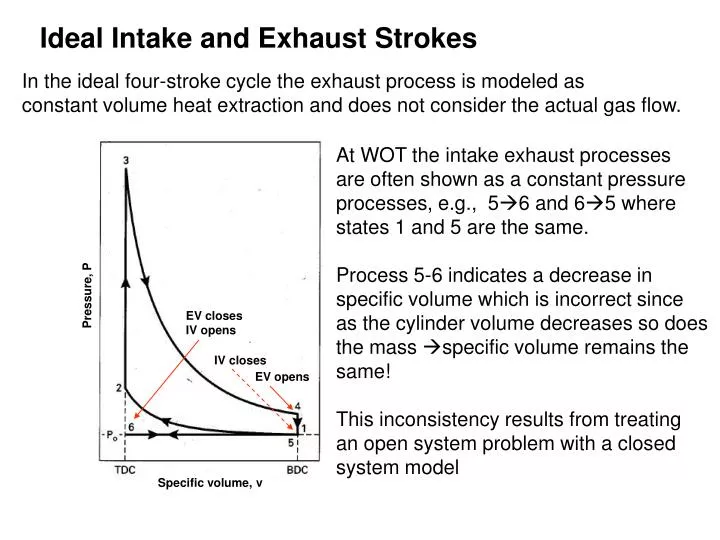
Ideal Intake and Exhaust Strokes. In the ideal four-stroke cycle the exhaust process is modeled as constant volume heat extraction and does not consider the actual gas flow. At WOT the intake exhaust processes are often shown as a constant pressure processes, e.g., 5 6 and 65 where

E N D
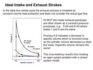
Ideal Intake and Exhaust Strokes In the ideal four-stroke cycle the exhaust process is modeled as constant volume heat extraction and does not consider the actual gas flow. At WOT the intake exhaust processes are often shown as a constant pressure processes, e.g., 56 and 65 where states 1 and 5 are the same. Process 5-6 indicates a decrease in specific volume which is incorrect since as the cylinder volume decreases so does the mass specific volume remains the same! This inconsistency results from treating an open system problem with a closed system model Pressure, P EV closes IV opens IV closes EV opens Specific volume, v
Valves operate instantaneously, intake and exhaustprocess are adiabatic and constant pressure. Unthrottled: Pi = Pe = 1 atm EV opens IV closes (state1) EV closes IV opens Throttled: Pi < Pe EV opens EV closes IV closes 6’ IV opens Supercharged: Pi > Pe IV opens 6’ 1 EV closes
Actual Exhaust Strokes The actual exhaust process consists of two phases: Pe Pi Ti Products State 4 (BC) State 5 (BC) State 6 (TC) Blowdown Displacement Blowdown – At the end of the power stroke when the exhaust valve opens the cylinder pressure is much higher than the exhaust manifold pressure which is typically at 1 atm (P4 > Pe), so the cylinder gas flows out through the exhaust valve and the pressure drops to Pe. Displacement – Remaining gas is pushed out of the cylinder by the piston moving to TC.
Blowdown Displacement 5 BC TC Blowdown • During the blowdown the gas remaining in the cylinder undergoes an isentropic expansion process (neglecting heat transfer) 5 (Otto/Diesel) • State 5 at the end of blowdown is a fictitious state corresponding to no actual piston location
Residual Gas The gas remaining in the cylinder when the piston reaches TC is called residual gas which mixes with intake gas (fuel-air for SI and air for CI) The residual gas temperature T6 is equal to T5 The Residual gas fraction f is defined as the ratio of the mass of residual gas to the mass of the fuel-air (assume ideal gas Pv = RT) Typically values of f are in the range 3% to 12%, lower in Diesels (larger r)
Intake Stroke 6 1 When the intake valve opens the fresh gas with mass mi mixes with the hotter residual gas with mass mR so the gas temperature at the end of the intake stroke T1 will be greater than the inlet temperature Ti. Applying conservation of mass: Ti Applying conservation of energy (open system):
Intake Gas Temperature (T1) Recall m6 = m1f and assuming ideal gas P6v6 = RT6 and h = cpT In terms of inlet and exhaust conditions P1 = Pi , P6 = Pe , T6 = Te
Valve Overlap In real engines valves don’t open and close instantaneously. In order to ensure that the valve is fully open during a stroke for volumetric efficiency, the valves are open for longer than 180o. The exhaust valve opens before TC and closes after BC and the intake valve opens before TC and closes after BC. At TC there is a period of valve overlap where both the intake and exhaust valves are open.
Valve overlap When the intake valve opens the cylinder pressure is at Pe Part throttle (Pi < Pe): residual gas flows into the intake port. During intake stroke the residual gas is first returned to the cylinder then fresh gas is introduced. Residual gas reduces part load performance. WOT (Pi = Pe): some fresh gas can flow out the exhaust valve reducing performance and increasing emissions. Supercharged (Pi > Pe): fresh gas can flow out the exhaust valve Pi Pe Pe Pi Supercharged Pi > Pe Throttled Pi < Pe
Valve Timing Conventional engines operate at low rpms, with idle and part load important High performance engines operate at high rpms at WOT, with power and volumetric efficiency important At high engine speeds less time available for fresh gas intake so need more crank angles to get high volumetric efficiency large valve overlap At low engine speed and part throttle valve overlap is minimized by reducing the angle duration for valves staying open.
Volumetric Efficiency • Volumetric efficiency is affected by : • Fuel evaporation • Mixture temperature • Pressure drop in the intake system • Gas dynamic effects Note: piston speed is proportional to air flow velocity
Factors affecting hv as a function of speed Fuel vapour pressure