Download
1 / 53
540 likes | 650 Views
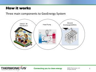
The Future of Structured Cabling A look into the next 10-15 years of Cabling Infrastructure Technology 2 BICSI RCDD, 2 NTS, 2 INSTALLER CREDITS Britt Johnson Berk-Tek Western Regional Manager. It simply works better. NetClear. Topics. The future for Fiber Optic Cabling

E N D
The Future of Structured Cabling Alook into the next 10-15 years of Cabling Infrastructure Technology 2 BICSI RCDD, 2 NTS, 2 INSTALLER CREDITS Britt Johnson Berk-Tek Western Regional Manager It simply works better. NetClear
Topics • The future for Fiber Optic Cabling • Existing fiber options • Upcoming IEEE standards • The effects of the IEEE standards on fiber infrastructure • Conclusions • The future for Copper Network Cabling • Noise and copper cable plants • Upcoming technology
Fiber Design Options • Three Physical Configuration Options • Field Terminated Cables and Connectors • Traditional installation method • Pre-terminated Cable Assemblies • Lowers total installation costs • Improved termination performance • Cassette based connectivity • High density terminations • Quick installation time
Cassette based solution • MTP/MPO connector factory terminated on a 12 fiber cable • Assembly connects to cassettes with choice of connectors • Allows for speed of install, re-usability, flexibility • Popular in data center environments
62.5 um Multi-Mode 160 MHz 200 MHz 500 MHz Single Mode Fiber SMF-28 Low Water Peak 50 um Multi-Mode 500 MHz (OM 2) 700 MHz 2000 MHz (OM 3) 4700 MHz 4900 MHz Fiber Options • Higher bandwidth glass will lengthen the distance an application works • “Excess bandwidth” can apply to reducing link loss budget
Standards Organizations • Technology advances come from Standards groups • IEEE 802.3 Ethernet Electronics Vendors • ISO 11801 European Version of IEEE • TIA Cabling Vendors • Vision into IEEE/ISO 11801 will provide roadmap for direction of cabling infrastructure
Campus Backbones Corporate Backbones Corporate Data Centers ISP Aggregation HighPerformanceComputing (HPC) Large Enterprise Data Centers Internet eXchanges running 10 Gb/s ISP Backbones connecting 10 Gb/s Content Providers wanting to push more to users 08 09 10 11 12 13 14 15 16 15 16 17 Year 20-- High Speed Roadmap Higher Speed Ethernet Market Adopters
Project Number: P802.3ba 5.5 Need for the Project: The project is necessary to provide a solution for applications that have been demonstrated to need bandwidth beyond the existing capabilities. These include data center, internet exchanges, high performance computing and video-on-demand delivery. Network aggregation and end-station bandwidth requirements are increasing at different rates, and is recognized by the definition of two distinct speeds to serve the appropriate applications. • High Speed Study Group (HSSG) to focus on providing a data center oriented solution
Study Group Task Force approved Sponsor Ballot TF Review WG Ballot Standard CFI J A S O N D 2006 J F M A M JJ A S O N D 2009 J F M A M 2010 J F M A M JJ A S O N D 2007 J F M A M JJ A S O N D 2008 D2.0 Last Feature D1.0 Baseline Proposal D3.0 Last Technical Change HSSG Development Plan
High Speed Study Group • IEEE 802.3ba (HSE) objectives from a cabling perspective: • Support 40G and 100G: • At least 1m over a backplane • At least 10m on copper cabling (twinax) • At least 100m on OM3 (2000 MHz MM glass) • At least 10km on SMF (metro and enterprise) • At least 40km on SMF (long-haul)
100M over OM3 fiber • Discussion Points • Transmission method • Impact on number of fiber strands • Connector types • Distances at 40G and 100G • What happened to OM2 fiber? • Single-Mode VS Multi-mode • Preparing for 40G/100G today
Transmission Method 12 Channel Duplex 2 Lambda 12 Channel Duplex 100 Gb/s 850 VCSEL Array • 2 x 6 x 10 Gb/s • One 12 fiber ribbon/MPO • 12 x 10 Gb/s • Two 12 fiber ribbons/MPO • MM 1G/10G uses Serial transmission scheme • 1 fiber dedicated Tx, 1 fiber Rx • 40G/100G to use parallel transmission • 10 fibers at 10G ea. Tx • 10 fibers at 10G ea. Rx • 12F MTP/MPO connector • 24 fiber MM cable • Possible 12F solution using CWDM
Multi fiber connector • MTP is only viable connector option as this point in time
Transmission method • SM option will likely use Coarse Wave Division Multiplexing • 4 lasers combined into one fiber • 1 fiber Tx, 1 fiber Rx • 2 fibers total • 40G/100G lasers do not exist and will be too expensive • Low water peak SM fiber better suited to CWDM
Lower loss 1.2 wavelength (nm) S C O E L Conventional SM Fiber 0.9 0.6 Loss (dB/km) 0.3 0 Coarse Wavelength Division Multiplexing (20 nm spacingITU-T G.694.2) 1300 1400 1500 1600 Wavelength (nm) Enables Full-Spectrum CWDM Low/Zero water peak fiber
LED’s used in lower speed fiber transmissions (100 Mb/s) VCSEL’s (low cost laser’s) replace LED’s at 1 GB/s speeds and up VCSEL’s have a non-uniform power dispersion Distances Encircled Power 3D Power map
Power in high DMD modes relatively low, causes secondary pulse very low amplitude, overallpulse detectable as one. Distances VCSEL DMD causes bit errors. Power concentrated in many modes with high delay, causes split pulse LED All Modes
Distances • Manufacturing process for parallel transmission contains a high scrap rate • Mounting 12 VCSEL’s on wafer difficult • Manufacturer’s want to loosen specification • Spectral width • Encircled flux • Looser VCSEL specification increase the effects of DMD • Higher DMD results in less distance • OM2 distance with new VCSEL’s is too short • OM3 becomes minimum bandwidth fiber • OM4 to be included in standards (4500 Mhz or 500M at 10G)
OM4 fiber (OM-3+) • Targeting a bandwidth of 4500 MHz • Distance at 10G 500M • Targeting a distance of over 200M for 40/100G • Berk-Tek sells the current maximum fiber bandwidth at 4900 MHz. • GigaLite 10XB fiber for 600M at 10G • Best shot at longer distance 40G/100G
Single-Mode VS Multi-mode • Single Mode CWDM Systems Work continues to define technical and economic feasibility of designs being considered • Pro: Low cable cost • Con: High Transceiver cost & development required • OM3 Multimode Parallel Systems 10 Gb/s VCSELS and fiber are already available • Pro: Low cost, readily available parts • Con: High cable cost and sensitivity to length • Traditionally, cost of electronics drive cost comparisons between MM and SM • Preliminary cost analysis for MM suggests lower cost up to ~200 meters
Specifying for 40G/100G • Specify low loss solutions • Berk-Tek/Ortronics performance above the standards • Lower loss for channel or • More connection points or • Longer distances • Ortronics low loss MTP cassettes • .5 dB premium performance cassettes
Specifying for 40/100G • Use smaller OD cables • Ribbon cables too big and bulky New 48F MDP Cable (0.231” OD) 24F (0.189” OD) 48F Stacked Ribbon Cable (0.520” OD)
Comparison: MDP to Ribbon New 48F MDP Cable (0.231” OD) 48F Stacked Ribbon Cable (0.520” OD)
Specifying for 40/100G • Use highest bandwidth fiber to insure longest length/ lowest loss budget • 150M at 10G (700 MHz) is out of standard • 300M at 10G (2000 MHz) is 100M at 40G • 550M at 10G (4500 MHz) is >100M at 40G • 600M at 10G (4900 MHz) gives customer best shot • Only available from OFS glass
Mandrel (Inert) Initial layers have high density • OVD Soot Deposition • All Soot layers deposited • prior to sintering • Density decreases as boule • becomes larger • Soot exposed to contamination OVD Torch Gas Mixture Traditional OVD Deposition Process
Drying/Sintering Furnace Mandrel removed Void left Furnace 1100-1500 oC Initial layers can now have cracks, defects Gas Mixture (Cl2) OVD Drying/Sintering Process • Soot sintered to form glass • GeO2 redistribution by Cl2 and density • variations cause index profile deformation • Void collapses causing index variation • with possible defects at center
End View Core Clad Distances • Each layer sintered prior to deposition of the next layer • Inside process is immune to contamination Results in superior control of Refractive Index Profile (therefore DMD & BW), Attenuation, Geometry
The Future for Copper • No current IEEE work in progress on 40G copper • Manufacturer’s and research institutions have begun preliminary modeling • Berk-Tek and University of PA • Transceiver manufacturer’s • Possible to look at UTP/FTP technology and draw reasonable conclusions about copper roadmap
Copper Cabling Technology • Cabling design is all about reducing the impact of noise on the signal • Maximize signal strength • Decrease noise • Cables can reduce noise • Twist rate, insulation, separation, precision reduce internal noise • Consistency and precision of manufacturing process and shielding can reduce external noise
Internal noise in cables • Internal Noise is unwanted signals jumping from one pair to an adjacent pair • NEXT, FEXT, ELFEXT, PSNEXT, PSELFEXT • The higher the application speed the less noise the system can handle • Higher speed Ethernet (1G and 10G) must use sophisticated internal noise cancellation techniques • Can internal noise at 40G be reduced enough for UTP cable?
External Noise Sources • Electromagnetic interference (EMI) • Narrow spikes of voltage • Generated by copy machines, air conditioning units, elevators, etc. • Radio Frequency Interference (RFI) • Conflicting frequencies with Ethernet (60-120 MHz) • Alien cross-talk • Unwanted emissions from cable to cable in a bundle • Same pair-pair (white –blue) alignments in separate cables coupling unwanted emissions
Cable Balance • Precise manufacturing of the pairs will allow a cable to absorb some external noise • Concentricity of conductors and strand • Even application of dielectric material • Consistent twist pattern • Measured as LCL, ELTCL (cable balance) • Efficient at reducing EMI and RFI to acceptable levels
Data Competency Center supporting tests EFT, RFI, Temperature, transceiver variability, 10G modeling, maximum distances 10GBase-SR, proximity to power, etc.
EFT Test • 90 M of 5e, 5E, 6 installed in wiremold raceway with 0” separation from power cable • Haefley generator introduced EFT pulses increasing to 1000V • Etherpeak generated Gigabit Ethernet traffic and measured packet loss
External Noise and UTP • Alien Crosstalk • Crosstalk (noise) occurring between adjacent cables in a bundle • Occurs at Near End of cable plant (ANEXT) • Occurs at Far End of cable plant (AELFEXT) • High speed cabling design tries to reduce Alien Crosstalk • Higher twist rates • Separation (larger sizes and lays) • Result is a larger OD cable
Cat 6 Cat 6a External Noise • Two options for reducing external noise Shielding Spacing
ANEXT and AFEXT VS TIA FTP and UTP • FTP shows greater margin over TIA than 6A, especially at higher frequencies.
Shielded (FTP) cable design • Two approved versions • FUTP or FTP (Class E) • IEEE requirements • TIA requirements • 6AFTP • Category 7 (Class F) • ISO 11801 European • Individually shielded pairs with an overall braid
Recap key points for UTP • UTP cable is all about signal strength VS Noise • Noise is external and internal • The higher the application speed, the less tolerance for noise • Internal noise can be cancelled to acceptable levels • External noise a major design hurdle • Spacing and shielding have been used to push UTP cable to 100M at 10G
The future for cable • 40G over copper • 2000 MHz frequency • Extremely low noise tolerances • Technology not available today to make UTP work • Some type of shielded cable likely for 100M operation • Characterized to high frequency • Multiple shielding • Heavier gauge wire • Thicker insulation Why did I ever switch from IBM Type 1!
The future for outlets 4 Pairs on top 250 MHz 8 top contacts 100% RJ45 compatible 4 new contacts For >600MHz 2 Pairs on top 2 Pairs on bottom 600 MHz Switch mechanism Only 8 contacts at a time
Server Trends:Ethernet Ports Source: Intel & Broadcom (April 2007) Millions 10-15 year transition for 1G Ethernet x86 Servers by Ethernet Connection Speed (40G and 100G)
Fiber and Copper review • Changes in current fiber standards development process will affect fiber cable plant designs for 40G • Parallel transmission technology • 24 strands per node • MTP/MPO connection styles • Changes in transceiver manufacturing to drive increases in glass bandwidth • OM3 at a minimum at 100M • Copper roadmap is a long time out • UTP technologies may be challenged • Some type of shielded technologies likely • 10G cabling today will last 10-15 years
THANK YOU QUESTIONS? It simply works better. NetClear
Higher speeds = less noise tolerance ____________________________________________________________________________________ ____________________________________________________________________________________ ____________________________________________________________________________________ ____________________________________________________________________________________ Source: Agilent Reduced State to State Voltage Increases Sensitivity and Error Generation