Download
1 / 32
320 likes | 479 Views
Assessment of emission and signal propagation in electrical power systems in the 2 - 150 kilohertz range MO-AM3-2 Anders Larsson, Luleå University of Technology, Sweden. Outline of the presentation Signal emitting equipment Measurement equipment Long term measurement

E N D
Assessment of emission and signal propagation in electrical power systems in the 2 - 150 kilohertz range MO-AM3-2 Anders Larsson, Luleå University of Technology, Sweden
Outline of the presentation • Signal emitting equipment • Measurement equipment • Long term measurement • High frequency components • Emissions fluorescent lamps powered by HF-ballast • Summary
Some signal emitting equipment in the frequency range from 2 to 150 kHz SMPS Concentrator Power line communication Power Meter
IEC 61000-4-7 Resulting spectra 2 to 150 kHz
Measurement at a house containing both electronic equipment together with PLC Induction cooker PLC
Instrumentation Current and voltage probes Memory recorders PQ instruments Oscilloscopes Measuring receivers
Long-term measurements where carried out in different locations:
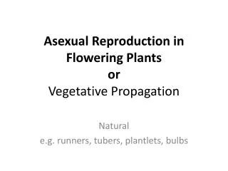
0 to 48 lamps project Spreading of components in the range of 2 to 150 kHz
Measurement setup Individual lamp current is also measured Itot and U is measured
Resulting voltage spectrums Primary emission Secondary emission
What about the recurrent oscillations? Peak amplitude of Itot
Summary • Most of the distortion in this frequency range can be classified into: • Narrowband components • Broadband components • Recurrent oscillations • Our experience is that PLC generates the highest levels of emission in this frequency range in the LV power systems • The emission from different ballast varies • Cont->
When this equipment is installed in large numbers the components aggregate in different ways. This impacts how emission standards should be carried out • The use of time-domain sampling instruments should be used even for the frequency range 9 – 150 kHz • Different analyzing tools are needed to detect and quantify different components. It is shown that not only one analyzing tool should be used to disclose and describe different components in the measured signal • Work is needed to close the gap in emission, compatibility and immunity standards
Further reading • Larsson, A & Bollen, M 2009, 'Emission and immunity of equipment in the frequency range 2 to 150 kHz', i L Toma & B Otomega (red), 2009 IEEE Bucharest PowerTech Proceedings, IEEE, Piscataway, N.J., s. 2325-2329. • Rönnberg, S, Wahlberg, M, Bollen, M, Larsson, A & Lundmark, M 2009, 'Measurement of interaction between equipment in the frequency range 9 to 95 kHz', CIRED 20th International Conference on Electricity Distribution, I E T Conference Publication Series, The Institution of Engineering and Technology, s. 231-234. • Bollen, M, Ribeiro, P, Larsson, A & Lundmark, M 2008, 'Limits for voltage distortion in the frequency range 2 to 9 kHz', I E E E Transactions on Power Delivery, vol 23, nr 3, s. 1481-1487. • Larsson, A, Bollen, M, Wahlberg, M, Lundmark, M & Rönnberg, S 2010, 'Measurements of high-frequency (2-150 kHz) distortion in low-voltage networks', I E E E Transactions on Power Delivery, vol 25, nr 3, s. 1749 - 1757. • Larsson, A & Bollen, M 2010, 'Measurement result from 1 to 48 fluorescent lamps in the frequency range 2 to 150 kHz', 14th International Conference on Harmonics and Quality of Power (ICHQP), IEEE, Piscataway, NJ . • Larsson, A 2011, On high-frequency distortion in low-voltage power systems, Doctoral thesis / Luleå University of Technology, Luleå tekniska universitet, Luleå.
Biography – Dr. Anders Larsson • 2011 – Lecture, Luleå University of Technology • 2011 – Ph.D, Luleå University of Technology • 2007 – Licentiate degree, Luleå University of Technology