Download
1 / 13
130 likes | 253 Views
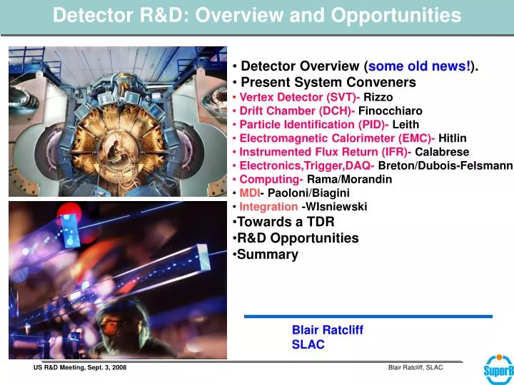
Detector R&D: Overview and Opportunities. Detector Overview ( some old news! ). Present System Conveners Vertex Detector (SVT)- Rizzo Drift Chamber (DCH)- Finocchiaro Particle Identification (PID)- Leith Electromagnetic Calorimeter (EMC)- Hitlin

E N D
Detector R&D: Overview and Opportunities • Detector Overview (some old news!). • Present System Conveners • Vertex Detector (SVT)- Rizzo • Drift Chamber (DCH)- Finocchiaro • Particle Identification (PID)- Leith • Electromagnetic Calorimeter (EMC)- Hitlin • Instrumented Flux Return (IFR)- Calabrese • Electronics,Trigger,DAQ- Breton/Dubois-Felsmann • Computing- Rama/Morandin • MDI- Paoloni/Biagini • Integration -WIsniewski • Towards a TDR • R&D Opportunities • Summary Blair Ratcliff SLAC
Detector Overview • Current B-Factory detectors have proven to be extremely effective instruments over the very broad physics program accessible at the U(4S). • Two (+1) examples: BaBar, Belle (Cleo-II). • Serve as “world class prototypes” for SuperB! • Optimized differently, but all were (are!) effective physics instruments. Comparisons between them help to define optimal strategies for subsystems in a SuperB detector. • CDR detector design based on BaBar (with re-optimization). • SuperB machine acceptance limits similar to PEP-II: BaBar’s geometry, field, and portions of several subsystems are rather close to optimal, Re-use of BaBar gives excellent performance and saves money. 2
Directions for Detector Optimization • From Machine and Environment: • Smaller Boost (7x4 GeV; bg=0.28) Smaller radius beam-pipe to retain adequate vertex resolution. Larger barrel acceptance. More particles backward in detector with somewhat softer spectrum forward. • Some (though not all) components of machine background components will be substantially larger. Improve detector segmentation Improve detector speed Improve radiation hardness and machine monitoring • From physics goals, which emphasize rare decays, LFV in t physics, and recoil (n) physics • Would like best possible hermeticity, with good subsystem efficiency and performance. • ~x100 Luminosity Improved trigger, DAQ, & computing (~15 years later) • Last, but not least, must replace aging components and technologies. 3
CDR Detector Layout – Based on Babar BASELINE New detector elements OPTION 4
Detector Evolution-B Factory to SuperB Factory • With careful attention machine design and shielding in the IR, the backgrounds at a SuperB should be ~ to those we know (and love?) at BaBar An excellent SuperB detector is possible with ~ today’s technology • CDR Baseline based on BaBar. It reuses • Fused Silica bars of the DIRC • DIRC & DCH Support • Barrel EMC CsI(Tl) crystal and mechanical structure • Superconducting coil & flux return (with some redesign). • Some elements have aged and need replacement. Others require moderate improvements to cope with the high luminosity environment, the smaller boost (4x7 GeV), and the high DAQ rates. • Small beam pipe technology • Thin silicon pixel detector for layer 0, and a new 5 layer SVT? • New DCH with CF mechanical structure, modified gas, cell size, cluster counting? • New Photon detection for DIRC fused silica bars? • Forward PID system (TOF in Baseline option) ? • New Forward calorimeter crystals (LYSO?). Backward EMC? Technology? • Minos-style extruded scintillator for instrumented flux return • Electronics and trigger- x100 real event rate • Computing- to handle massive date volume 5
CDRTDR • What decisions must be taken before the TDR can be written? • What is the mechanism for reaching those decisions? How can missing information be obtained? • What simulation tools are needed? • What specific R&D is needed? • What detailed design is needed? When can it begin? • What are the time scales for the decisions. If options are open, how can they be resolved and on what time scale? • How many physicists are involved now ? How many are needed? When? • Support for R&D, technical and design personnel? • How does the subgroup interact with the other subgroups and incorporate general detector design considerations
Examples of Decisions needed for TDR Internal System versus General Detector ExamplesInternal: What is the SVT layer 0 technology? How is the beam pipe constructed? What is the technology for the backward EMC? What is the DCH cell configuration? DIRC Barrel SOB? General: Will there be forward PID in SuperB? What is the effect of material on EC EMC? What is the front end data volume? Where is the interaction point? Where do the in-detector electronics reside? Not always a clean separation, but general decisions will usually need an early resolution before the TDR. Some (not too many?) internal subsystem choices could remain in TDR.
R&D and TDR areas with (some) US involvement Subsystems • Particle Identification (PID)- Cincinnati, SLAC, Hawaii • Electromagnetic Calorimeter (EMC)-Caltech General Detector Systems • Electronics,Trigger,DAQ-SLAC • Detector Optimization and Bench Marking • Computing and Simulation- SLAC, LBL • MDI- SLAC, Ohio State • Integration –SLAC • TDR • General Status: Lots of impressive progress right before Elba especially in the general computing systems areas. (But limited since!) Note the general Detector meetings begin again tomorrow (Thursday, Sept 4 at 8:30). R&D Manpower available has been limited, especially from US. All existing US R&D areas welcome new people.
A brief review of Ongoing System R&D • Vertex Detector (SVT) • Drift Chamber (DCH) • Particle Identification (PID)-see Jaroslav’s talk • Electromagnetic Calorimeter (EMC)- see Dave Hitlin’s talk • Instrumented Flux Return (IFR) • Computing • MDI • Integration
90Sr electrons S/N=23 Landau mV APSEL4D - Fe55 5.9 keV calibration peak APSEL4D - 32x128 pixels 50 mm pixel pitch Cluster signal (mV) Noise events APSEL4D – Sr90 test Fired pixel map with threshold @ ½ MIP Good uniformity (the source was positioned on the left side of the matrix MAPS selected results Basic CMOS MAPS R&D (most challenging option for the Layer0): • Optimization of the Deep NWell MAPS pixel • S/N up to 25 with power consumption reduced (~30 uW/ch) • Fast readout architecture (sparsifycation and timestamp) implemented in a 4k pixel matrix. • Preliminary test encouraging. • Noise and threshold dispersion at the same level ~ 65 e- • Good sensitivity to e- from Sr90 and to g from Fe55 source
T-1,2,3,4 :reference telescope modules Striplets-2 S2 T-4,3 T-2,1 MAPS-1 beam MAPS-2 Striplets-1 S3 S1 Test Beam Starting now at CERN Main goals: • DNW MAPS matrix resolution & efficiency • Thin (200 um) striplets module with FSSR2 readout chips (baseline option in the CDR) • Demostrate LV1 copability with tracker information sent to Associative Memories • New DAQ system developed for data push architecture • All the parts are getting ready: • CMOS MAPS chip with sparsified readout received and tested (G.Rizzo) • Beam telescope and striplets module in preparation (L. Vitale) • DAQ system under test (M. Villa) • Reco Software under development (N.Neri)
Update on Thin Mechanics/Cooling R&D for Layer0 (F.Bosi) Design of a pixel module with integrated cooling and low material (< 1% X0) • Crucial for a low material Layer 0 design with both MAPS & Hybrid Pixel options • Development of support structures with cooling microchannel integrated in the Carbon Fiber/Ceramics support • The total thickness of the support structure + cooling fluid + peek + glue is: 0.35 % X0 • Consistent with the requirements • Thermal simulation of the prototype module in progress • Testbench for thermoidraulic measurements in preparation. Prototype module simulated