Download
1 / 2
20 likes | 29 Views
Unasis Portable Swaging Tool Instructions<br><br>For More Details Please Visit: http://www.carterbearings.co.uk/aerospace-bearing-tools/aerospace-bearing-tool-visual-guides/

E N D
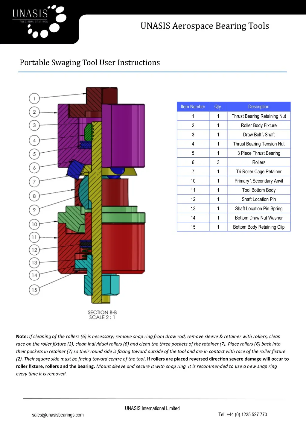
UNASIS Aerospace Bearing Tools Portable Swaging Tool User Instructions Item Number Qty. Description 1 1 Thrust Bearing Retaining Nut 2 1 Roller Body Fixture 3 1 Draw Bolt \ Shaft 4 1 Thrust Bearing Tension Nut 5 1 3 Piece Thrust Bearing 6 3 Rollers 7 1 Tri Roller Cage Retainer 10 1 Primary \ Secondary Anvil 11 1 Tool Bottom Body 12 1 Shaft Location Pin 13 1 Shaft Location Pin Spring 14 1 Bottom Draw Nut Washer 15 1 Bottom Body Retaining Clip Note: If cleaning of the rollers (6) is necessary; remove snap ring from draw rod, remove sleeve & retainer with rollers, clean race on the roller fixture (2), clean individual rollers (6) and clean the three pockets of the retainer (7). Place rollers (6) back into their pockets in retainer (7) so their round side is facing toward outside of the tool and are in contact with race of the roller fixture (2). Their square side must be facing toward centre of the tool. If rollers are placed reversed direction severe damage will occur to roller fixture, rollers and the bearing. Mount sleeve and secure it with snap ring. It is recommended to use a new snap ring every time it is removed. UNASIS International Limited Tel: +44 (0) 1235 527 770 sales@unasisbearings.com
UNASIS Aerospace Bearing Tools Portable Swaging Tool User Instructions Cont. Set-up Instructions Disassemble tool by carefully removing draw rod’s hex nut in Roller Fixture Assembly (items 1-7 stay together). Insert Roller Fixture Assembly into bearing so the sleeve (3) goes through the bore of the bearing (8 & 9) and so that the rollers (6) sit into the bearing’s V-groove. Prepare Locating Fixture Assembly (items 1 – 15) by placing locating ring (10) onto the bearing base (8) in a way so its flat side (PRIMARY) is opposite to thrust bearing set (11) and retaining snap ring (10). Mount Locating Fixture Assembly through draw rod on opposite side of bearing. Hand-tighten the nut until rollers are snug inside the V-groove of the bearing. Ensure the locating fixture ring’ primary side is flush with the face of the bearing’s outer race and the housing. Note: Never over tighten causing rollers to dent or make an impression in bearing’s groove lip. Ensure that the flat face (primary) of the locating ring is supporting both the bearing and the housing. 1) 2) 3) 4) Operating Instructions 1) 2) Rotate roller fixture by hand to ensure there are no restrictions. Tighten bottom hex nut on locating ring side clockwise approximately 30 degrees causing rollers to press against lip. Use wrench but don’t over tighten! Rotate roller fixture three complete revolutions or until it rotates without resistance. Use spanner wrench on Top Thrust Bearing Retainer Nut to assist with rolling the assembly. Always rotate in a clockwise direction. Repeat rotation and tightening until the bottom nut is rotated 270° - 360° or until the bearing’s lip is completely swaged and there is no gap larger than (.002” - .005”) between the lip and housing or until it meets the given OEM specification. Remove the bottom Locating Fixture Assembly from the Roller Fixture Assembly by first removing the bottom hex nut For double sided V-groove bearings, flip the Roller Fixture Assembly around so that rollers are now on the other side of the bearing in order to swage opposite side. Prepare Locating Fixture Assembly by placing locating ring (10) onto the base (11) in a way so its angled side (SECONDARY) is opposite to thrust bearing set and bottom nut. Mount Locating Fixture Assembly through draw rod on opposite side of bearing. Hand-tighten the bottom nut until rollers are inside the V-groove of the bearing and locating ring’ secondary side sits against swaged lip of the bearing. 3) 4) 5) 6) 7) 8) Note: Never over tighten causing rollers to dent or make an impression in bearing’s groove lip. Ensure that the angled side (secondary) of the locating ring is supporting only the swaged portion of the bearing 1) 2) Repeat steps 5 through 9 to swage the opposite side of the bearing. Dismount Locating Fixture Assembly and Roller Fixture Assembly from completely swaged bearing. Examine quality of swaged lip. Re-swaging is allowable if the gap on the lip is excessive. Mount Swaging Tool’s segments back together, lightly oil and store away. 3) UNASIS International Limited Tel: +44 (0) 1235 527 770 sales@unasisbearings.com 15