Download
1 / 33
330 likes | 806 Views
Non Arc Welding Processes Resistance Weld High Energy Density Friction Welding Brazing & Soldering Plastics Joining. Non-Arc Welding Processes (Part 1). Lesson Objectives When you finish this lesson you will understand: Resistance Weldability and Various Resistance Welding Processes

E N D
Non Arc Welding Processes Resistance Weld High Energy Density Friction Welding Brazing & Soldering Plastics Joining
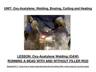
Non-Arc Welding Processes (Part 1) • Lesson Objectives • When you finish this lesson you will understand: • Resistance Weldability and Various Resistance Welding Processes • Oxy-fuel welding and cutting principles • Solid state welding processes and comparisons between them • Advantages and disadvantages of each process • Learning Activities • Read Handbook pp 16-30 • Look Up Keywords • View Slides; • Read Notes, • Listen to lecture • View Video • Do on-line workbook • Do Homework Keywords: Resistance Spot Welding, Seam Welding, Spot Weldability Lobe, Oxy-Acetylene Torch, Friction Welding, Diffusion Welding, Ultrasonic Welding, Explosive Welding
Introduction Non-Arc Welding Processes • Resistive heating, chemical reactions, focused light and electrons, sound waves, and friction can also be used to join materials • Resistance welding • Oxy-Fuel Welding • Friction welding (&Solid State) • Laser and electron beam welding • Brazing and soldering • Plastics joining • Adhesive bonding
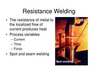
Resistance Welding Resistance Welding • The resistance of metal to the localized flow of current produces heat • Process variables • Current • Time • Force • Spot and seam welding Spot welding
electrode electrode Spot Weld
Resistance Welding Electrodes • Electrode tips wear during service, causing nugget size to decrease • Zinc-coating on steel alloys with copper electrodes to form brass • Copper base materials, divided into classes Truncated cone Dome Pointed
Resistance Welding Operating Window - Lobe Curve Constant electrode force Acceptable nugget size Time (cycles of current) Nugget too small Expulsion Current (1000’s of amperes)
Roll spot weld Overlapping seam weld Continuous seam weld
Resistance Welding Advantages • High speed, < 0.1 seconds in automotive spot welds • Excellent for sheet metal applications, < ¼-inch • No filler metal
Resistance Welding Process Disadvantages and Limitations • Higher equipment costs than arc welding • Power line demands • Nondestructive testing • Low tensile and fatigue strength • Not portable • Electrode wear • Lap joint requires additional metal
Videos Link to the “Resistance Welding Videos from the Video Page on the WE300 Webpage
Questions? • Turn to the person sitting next to you and discuss (1 min.): • If the Lobe Curve represents the welding parameter combinations which produce good welds, why do so many of the automotive spot welds have expulsion? • Turn to the person sitting next to you and discuss (1 min.): • When spot welds are place too close to one another, some of the current from the second weld shunts thru the first. Why then can overlap seam welds work when the welds are so close that they overlap?
Introduction Non-Arc Welding Processes • Resistive heating, chemical reactions, focused light and electrons, sound waves, and friction can also be used to join materials • Resistance welding • Oxy-Fuel Welding • Friction welding (&Solid State) • Laser and electron beam welding • Brazing and soldering • Plastics joining • Adhesive bonding
( Oxygen from torch) (Oxygen from Air) Linnert, Welding Metallurgy, AWS, 1994
Thermite Welding Power Fe2O3 + 2Al > 2Fe + Al2O3 + heat Base Metal Liquid
Questions? • Turn to the person sitting next to you and discuss (1 min.): • The oxy-fuel and that thermit welding are both chemical burning reactions. In the first oxygen is supplied by oxygen gas, in the thermit welding, it is supplied by the iron oxide. Why does this aluminum “burning” in the thermit welding work?
Introduction Non-Arc Welding Processes • Resistive heating, chemical reactions, focused light and electrons, sound waves, and friction can also be used to join materials • Resistance welding • Oxy-Fuel Welding • Friction welding (&Solid State) • Laser and electron beam welding • Brazing and soldering • Plastics joining • Adhesive bonding
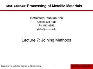
Solid-State Welding • Processes that produce a weld through the application of pressure at a temperature below the melting temperature of the base material; no filler metal is used • Friction welding • Diffusion welding • Ultrasonic welding • Explosion welding 0.1.1.2.2.T9.95.12
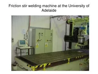
Friction Welding (FRW) 0.1.1.2.2.T10.95.12
Friction Welding Friction Welding - Advantages • For correct part geometry, friction welding is faster than most other processes • Can join dissimilar materials together • Copper to steel or aluminum • Easily automated for high volume production • Can join plastics
Friction Welding Limitations of Friction Welding • Start-up cost is high • Parts must be able to rotate about an axis of symmetry • Free machining alloys are difficult to weld • Non-forgeable materials cannot be friction welded
Diffusion Welding Working Principles 1st stage deformation and interfacial boundary formation • 1st stage • deformation forming interfacial boundary. • 2nd stage • Grain boundary migration and pore elimination. • 3rd stage • Volume diffusion and pore elimination. asperities come into contact. 2nd stage grain boundary migration and pore elimination 3rd stage volume diffusion pore elimination
Ultrasonic Welding • Advantages • Fast • Can spot or seam weld • Limitations • Equipment complex, many variables • Only use on small parts • More on this below for plastics
Principles of Explosion Welding Detonator Explosive • Welding arrangement consists of three components - • Base component • Prime component • Explosive. • Base component remains stationary, supported by anvil. prime component Base component Component arrangement for explosion welding
Detonation Principles of Explosion Welding • Prime component is placed either parallel or at an angle to the base. • Explosive is distributed over top surface of prime component. • Upon detonation, prime componentcollides with base component to complete welding. Prime component Weld Jet Base component Action between components during explosion welding.
Linnert, Welding Metallurgy, AWS, 1994
Questions? • Turn to the person sitting next to you and discuss (1 min.): • In friction welding, the outer part of the bar is moving faster and will therefore have more heating than the exact center of the bar. What might you do to “even out” the heating across the entire interface?
Homework Do Special Project Homework on Solid State Welding