Download
1 / 59
590 likes | 821 Views
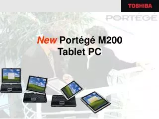
Using an M200 OTDR For M200 Version 1.0.6 released November 2006. Outline. Features Test Modes Full Auto Live Expert Main Menu Set Up Test Settings File Settings General Settings Event Settings Testing File Management. Features of the M200. Single-mode, Multimode and ‘Quad’ models

E N D
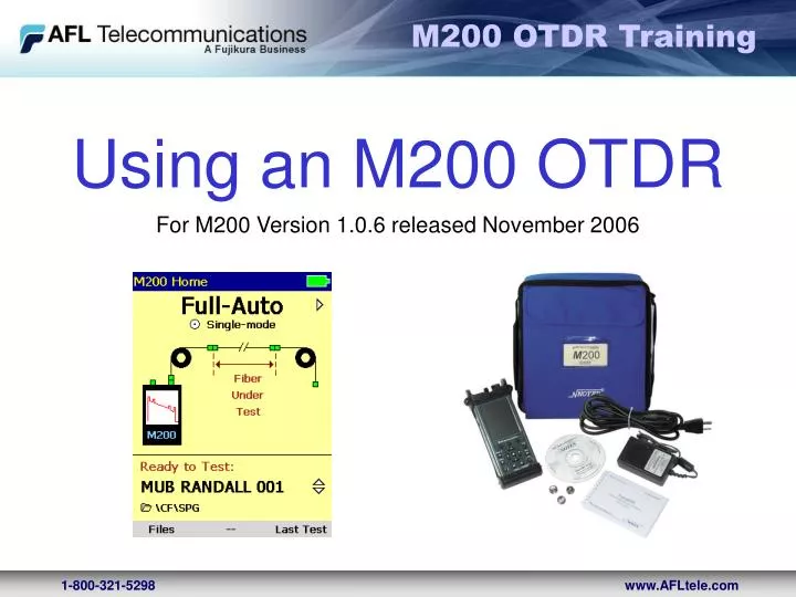
Using an M200 OTDR For M200 Version 1.0.6 released November 2006
Outline • Features • Test Modes • Full Auto • Live • Expert • Main Menu Set Up • Test Settings • File Settings • General Settings • Event Settings • Testing • File Management
Features of the M200 • Single-mode, Multimode and ‘Quad’ models • Short event / attenuation dead zones • (1.5 / 9 m typical) • Intermediate range (26 dB) good for access, FTTH, and premises fiber networks • Hand-held (1.9 lb)
Features of the M200 • Li-ion battery: • ~ 8 hour operating time • Tool-free battery door • New, graphical user interface with web-like PREV / NEXT keys to view results
Features of the M200 • Test, View, & Save As in trace pairs 850/1300nm or 1310/1550nm
Features of the M200 • Tool-free, changeable test port adapters • SC, FC, ST included (LC available-call factory) • Trace600 software (free-ware) • Internal & Compact Flash data storage • Store 1000’s of traces
Features (cont.) • Transflective Color Display • Crisp and bright indoor & in direct sunlight • Dedicated Test & Save Keys • Integrated VFL (650 nm)
Features (cont.) • Quick disconnect integrated into boot for wrist strap or other hanging devices • USB port to transfer data to PC using ActiveSync
Features (cont.) • Rich file naming and folder setup • Standard Bellcore.SOR trace file format • (GR-196)
Features (cont.) • Touch-screen may be used for text entry
M200 Set Up & Home Page
Home Page • M200 start-up page • If user hits Back/home key successively, they will get to this screen after exiting other screens • Allows access to File Manager for reviewing Traces on the M200 and managing the files and folders
Home Page Test Modes • Full Auto, Live or Expert Test Mode is selectable from the Home Page using • buttons • Fiber Type (shown as Single-mode) is not selectable from the home page
Home Page Launch & Receive 1 Launch & 2 Receive cables are specified in the test set up Launch cable only specified in the test set up 1 2 1 Fiber Ring Launch/Receive
Home Page Next Tests • Name for next test: • SMITH HALL 001 • Fiber Number of the next test, can be incremented from 001 to 999 using the buttons • File Storage: as shown next tests will be stored to Compact Flash (CF) in the folder named SPG
Main Menu TEST SETTINGS
Test Settings: Main Menu -Test Tab Access Main Menu by pressing at the Home Page Test is the first Tab in all test modes Full Auto Live Expert Auto Expert Manual
Test Settings: Sub Menus Parameters followed by “…” indicate there is a submenu. To access, highlight the parameter and press select the button Fiber Type: Use default setting or refer to manufacturers fiber specifications for the fiber under test
Test Settings: Main Menu - File Tab Use to create a New Folder or to Change the Folder into which the Next Test Traces will be saved. • Highlight Folder… • Press the button to open the File Manager • Use and buttons to choose an existing file • Or Press Tools, use the down arrow to select New Folder to create a new folder Tools Pop up menu
File Name Format Name Format – user selectable [Cable_Fiber] or [Far_Fiber] SMITH HALL_001_S13.sor Wavelength indicator- added by M200 Fiber number –user set, will auto increment File name prefix – user defined
Test Settings: Main Menu - General Tab • Distance Units: select the units to be used for distance measurements: • Meters, Kft, Km, Miles, Feet • Beeper: Audible tone On or Off • Language:Select English or other available language. OTDR must restart to make current • View Version: Important for calls to Tech Support or for upgrading the M200
Test Settings: Full Auto Mode • Select the Mode by using • Full Auto, Live, Expert • Select the Test Port type by using • Single-mode or Multimode • Specify if using Launch &/or Receive cables, and their respective length • Full Auto tests will be performed at two wavelengths per test: • 850/1300nm for Multimode • 1310/1550nm for Single-mode Main Menu Test Tab
Test Settings: Live Mode With the Mode line highlighted use the buttons to select Live • Specify a Range: 1.5 to 2 x length of fiber under test • Live tests will be performed at ONLY one wavelength per test: • 850 or 1300nm for Multimode • 1310 or 1550nm for Single-mode • Specify if using Launch &/or Receive cables, and their respective length
Test Settings: Expert Mode Auto Highlight the Mode line and use the buttons to select Expert Expert Auto uses default settings to perform a test but allows the user to test at a single wavelength if desired Expert Auto tests can be performed at one or two wavelengths per test: • 850 and/or 1300nm for Multimode • 1310 and/or 1550nm for Single-mode
Test Settings: Expert Mode-Manual With the Mode line highlighted use the buttons to select Expert In Expert Manual the user must know information about the fiber under test and how to set up an OTDR Expert Manual tests can be performed at one or two wavelengths per test: • 850 and/or 1300nm for Multimode • 1310 and/or 1550nm for Single-mode
Test Settings: Expert Mode - Manual Use buttons to specify the parameters for testing • Range: set to 1.5 to 2 x length of fiber under test including launch/receive cables • Pulse: (see next slides) • Narrow pulses are best for resolving close events but are limited to short links. • Wide pulses are good for measuring long links • Time (Averages): (see next slides) • Traces are always averaged over hundreds or thousands of pulses. • The trade-off is time vs. trace quality. • After about 3 min, you get very little additional improvement • Filter: selectable as On or Off, • Smoothes choppy traces. • As a rule of thumb use with PW 1us or greater
Range Too short: less than link length Good: about 1.5x to 2x link length Too long: much larger than link length Link Link Link Trace is “squashed” into left side of display Can’t see entire link – unpredictable results Good trace – can see end of fiber
Too narrow: Pulse Width About right: Too wide: Link Link Link Where is this this event? Trace “disappears” into noise floor Events can be seen and trace is smooth Can’t resolve events
Too few: Averages (Time) About right: Too many Link Link Link Trace is noisy – noise floor is too high Trace is smooth Trace is smooth but waste of time
Main Menu: Expert - Events Tab • Events: set to Auto or Off • Thresholds: set to Default or User • Auto Default will generate an Event Table using the M200 settings • Off will not automatically generate an Event Table
Main Menu: Expert - Events Tab • Events: set to Auto • ThresholdsUser • Press Select and adjust the parameters using the navigation buttons • Auto User will generate an Event Table using the users threshold parameter settings
Testing • Clean all connectors to be involved in testing • Connect Launch Cable to the appropriate Test Port and the Fiber Under Test • If using connect Receive Cable to far end of Fiber Under Test • Set the OTDR up as previously explained • Press Test
Trace View Tab Displays the: • OTDR Trace graphically • Trace set-up parameters • A and B cursor locations • Distance from A to B cursors in user selected distance units • Insertion Loss measured from the A to B cursor 1 Launch Cable 2 3 5 4
Trace View Tab (cont.) 1. Single-mode 2. Dual Wavelength 1310/1550nm 3. 150m Launch Cable 4. Trace is not yet saved 5. As shown traces will be saved: To the Compact Flash in the SPG folder as file: QA Box 001_S13.sor & QA Box 001_S15.sor 4 5 2 Launch Cable 3 1
Zoom Adjust – Trace View • From Trace View press the Zoom Adjust soft key • Zoom will occur around the “active” (solid cursor) • To change cursors press the select button • Use the Navigation buttons to adjust the zoom level • Press the soft key “OK” when finished zooming
Event Table Tab • Displays a graph of the OTDR trace plus test date in the event table • Event Locations • Event Type • Event Reflectance (dB) • Event Insertion Loss Generated for Full Auto & Expert Tests if Events is set to Auto
Event Table Tab • Event Icons Type Start End Reflective Event Non-Reflective Event Gainer Multiple Event
Event Table Tab • Touching the event in the table or using the navigation buttons will highlight and put the cursor on the event selected • The navigations buttons will zoom/un-zoom around the selected event cursor
Re-Calculate an Event Table • Press the soft key for “Re-Calc” if you desire to change a test parameter • This opens a window of parameters some which can be changed, (black text)
Calculate an Event Table • An Event Table is generated for Full Auto Tests & Expert Tests if Events is set to Auto • Press the soft key for “Calc” if an Event Table was not calculated
Summary Table Displays a graph of the trace Displays a table with • Link Length • Optical Return Loss (dB) • Insertion Loss (dB)
Saving a File - File Info Tab • Displays the fiber set up parameters of the currently displayed trace • Allows you to change the Name Format, Near, Far or Cable names, Fiber Number or Folder where the test will be saved
Saving a File • Press the dedicated Save key to save the file • You can save from the Trace, Event Table, Summary or the Save Tabs
File Management Opening Traces for Review Swapping from CF to Internal Tools
Opening a Saved Trace for Review To review saved traces Press the Files Soft Key from the Home Page to open the File Manager Use Navigation keys to select folders or files
Opening a Saved Trace for Review Use Navigation keys to select folders or files Use to move up or down the list of files/folders Use to move to the Top or Bottom of current list Press the select button with the up arrow line selected to go up a level
Opening a Saved Trace for Review Use Navigation keys to select folders or files Use to move up or down the list of files/folders, press the select key to highlight the file (file pair) you would like to review, press the open soft key to open the file
Swapping CF to Internal* • Use the navigation keys to select the drive you desire (will have red lines above and below it to show it is selected) Press the Select key to open that folder • If select was pressed in this example the CF folder would be opened *Note: you must have a CF card inserted in the M200
TOOLS • In file manager the soft key Tools opens a window to allow you to manage files: • Cut files/folders • Copy files/folders • Paste files/folders • Delete files/folders • Create New Folders • Rename files/folders • Select All • Select None
TOOLS (cont.) • If moving files it is recommended to copy and paste them not cut them • Assure you have made a successful copy before cutting or deleting files/folders Example: 1310nm tests selected for copying Up/down & select were used to select the tests