Download
1 / 10
100 likes | 304 Views
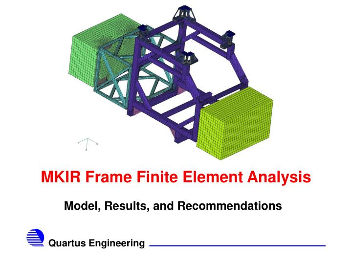
MKIR Frame Finite Element Analysis. Model, Results, and Recommendations. Corner Support Brackets. ISS Attachment Brackets. Main Frame to Extension Frame Angle Brackets. Main Frame. Extension Frame. Main Frame to E-Box Angle Brackets. Main Frame Gussets.

E N D
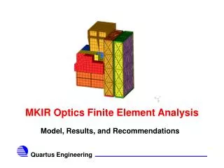
MKIR Frame Finite Element Analysis Model, Results, and Recommendations
Corner Support Brackets ISS Attachment Brackets Main Frame to Extension Frame Angle Brackets Main Frame Extension Frame Main Frame to E-Box Angle Brackets Main Frame Gussets Extension Frame to E-Box Angle Brackets Corner Support Plates Overall Model Description(E-Boxes Not Shown)
Modeling Assumptions • E-Boxes modeled as empty boxes with density modified to give correct weight • All angle bracket bolts modeled using a four bolt pattern • Recommended design change • Connections: • Angle and corner bracket connections are bolted • Extension and main frame tubing is welded • Main frame gussets are bolted to main frame • Attachment brackets are welded to the main frame • Corner support plates are welded to the main frame • Main frame to extension brackets rearranged to improve stress margins
Model Setup • Model Stats • 66,401 Nodes and 67,356 Elements • Entire model except bolts are linear quad thin shell elements • Bolts are linear DOF springs • Boundary Conditions • Clamped on corners of attachment bracket’s top face (Light Blue at left) • Loads • 1 G Applied in each orthogonal direction
Linear Static Stress Results(Main Frame) • 7177 psi max von mises stress occurs in Y load case
Linear Static Stress Results(Extension Frame) • 5082 psi max von mises stress occurs in Y load case
Results Discussion • All Margins are Positive G • Greater than 4 for frame structure • Greater than 2 for fasteners • Could be higher if bigger/better fasteners used • Using aluminum would triple the deflections, but would give the same stresses • More difficult to weld • Heat treatment probably necessary • Only provides weight savings, not increase in stress margins
Recommendations • Use four bolt pattern on each angle bracket face instead of two bolt pattern • Better handles moments on the brackets • Consider different positions for extension frame angles • Use configuration similar to the assumed location connecting main frame to e-box • More effective support for different load cases