Download
1 / 14
150 likes | 344 Views
MAGNETIC EFFECT OF CURRENT - II. Lorentz Magnetic Force Fleming’s Left Hand Rule Force on a moving charge in uniform Electric and Magnetic fields Force on a current carrying conductor in a uniform Magnetic Field Force between two infinitely long parallel current-carrying conductors

E N D
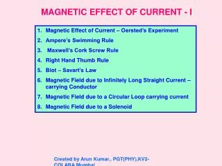
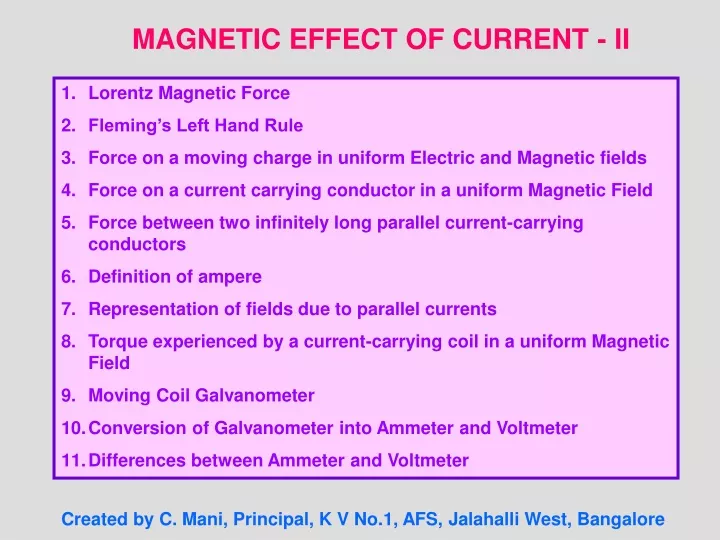
MAGNETIC EFFECT OF CURRENT - II • Lorentz Magnetic Force • Fleming’s Left Hand Rule • Force on a moving charge in uniform Electric and Magnetic fields • Force on a current carrying conductor in a uniform Magnetic Field • Force between two infinitely long parallel current-carrying conductors • Definition of ampere • Representation of fields due to parallel currents • Torque experienced by a current-carrying coil in a uniform Magnetic Field • Moving Coil Galvanometer • Conversion of Galvanometer into Ammeter and Voltmeter • Differences between Ammeter and Voltmeter Created by C. Mani, Principal, K V No.1, AFS, Jalahalli West, Bangalore
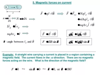
Fm = q (v x B) q θ Fm = (q v B sin θ) n B v F B v F I where θ is the angle between v and B θ + - I q Lorentz Magnetic Force: A current carrying conductor placed in a magnetic field experiences a force which means that a moving charge in a magnetic field experiences force. or • Special Cases: • If the charge is at rest, i.e. v = 0, then Fm = 0. • So, a stationary charge in a magnetic field does not experience any force. • If θ= 0° or 180° i.e. if the charge moves parallel or anti-parallel to the direction of the magnetic field, then Fm = 0. • If θ= 90° i.e. ifthe charge moves perpendicular to the magnetic field, then the force is maximum. Fm (max) = q v B
Force(F) Magnetic Field (B) When a charge q moves with velocity v in region in which both electric field E and magnetic field B exist, then the Lorentz force is F = qE + q (v x B) or F = q (E + v x B) ElectricCurrent (I) Fleming’s Left Hand Rule: If the central finger, fore finger and thumb of left hand are stretched mutually perpendicular to each other and the central finger points to current, fore finger points to magnetic field, then thumb points in the direction of motion (force) on the current carrying conductor. TIP: Remember the phrase ‘e m f’ to represent electric current, magnetic field and force in anticlockwise direction of the fingers of left hand. Force on a moving charge in uniform Electric and Magnetic Fields:
I F θ dl Force experienced by each electron in the conductor is f = - e (vd x B) l A B I vd - Force experienced by the electrons in dl is dF = n A dl [ - e (vd x B)] = - n e A vd (dl X B) = I (dl x B) F =∫ dF= ∫ I (dl x B) F= I (l x B) F = I l B sin θ Force on a current-carrying conductor in a uniform Magnetic Field: If n be the number density of electrons, A be the area of cross section of the conductor, then no. of electrons in the element dl is n A dl. where I = neAvd and -ve sign represents that the direction of dl is opposite to that of vd) or
Forces between two parallel infinitely long current-carrying conductors: Q S μ0 I2 μ0 I1 B2= B1= I1 I2 2π r 2π r F12 F21 B2 B1 r μ0 I1 I2l sin 90˚ F21= 2π r P R x μ0 I1 I2l μ0 I1 I2l F12= F21= 2π r 2π r μ0 I2 I1l sin 90˚ F12= 2π r μ0 I1 I2l μ0 I1 I2 F12=F21=F = F / l = 2π r 2π r Magnetic Field on RS due to current in PQ is (in magnitude) Force acting on RS due to current I2 through it is or B1acts perpendicular and into the plane of the diagram by Right Hand Thumb Rule. So, the angle between l and B1 is 90˚ . l is length of the conductor. Magnetic Field on PQ due to current in RS is (in magnitude) Force acting on PQ due to current I1 through it is (The angle between l and B2 is 90˚ and B2 Is emerging out) or N / m Force per unit length of the conductor is
Q S Q S I1 I1 I2 F F F F r I2 r x x x P R P R By Fleming’s Left Hand Rule, the conductors experience force towards each other and hence attract each other. By Fleming’s Left Hand Rule, the conductors experience force away from each other and hence repel each other.
I2 I1 I1 I2 B B N μ0 I1 I2 F / l = 2π r Definition of Ampere: Force per unit length of the conductor is N / m When I1 = I2 = 1 Ampere and r = 1 m, then F = 2 x 10⁻⁷ N/m. One ampere is that current which, if passed in each of two parallel conductors of infinite length and placed 1 m apart in vacuum causes each conductor to experience a force of 2 x 10⁻⁷ Newton per metre of length of the conductor. Representation of Field due to Parallel Currents:
Torque experienced by a Current Loop (Rectangular) in a uniform Magnetic Field: FSP S b I FRS FSP = I (b x B) P x B FQR = I (b x B) l R FPQ I Forces FSP and FQR are equal in magnitude but opposite in direction and they cancel out each other. Moreover they act along the same line of action (axis) and hence do not produce torque. θ θ Q FQR FPQ = I (l x B) Forces FPQ and FRS being equal in magnitude but opposite in direction cancel out each other and do not produce any translational motion.But they act along different lines of action and hence produce torque about the axis of the coil. FRS = I (l x B) Letθ be the angle between the plane of the loop and the direction of the magnetic field. The axis of the coil is perpendicular to the magnetic field. | FSP | = I b B sin θ | FQR | = I b B sin θ | FPQ | = I l B sin 90° = I l B | FRs | = I l B sin 90° = I l B
FRS n n S b Φ Φ P x B B FPQ I R I θ θ Q Torque experienced by the coil is ז= FPQx PN (in magnitude) ז = I l B (b cos θ) ז = I lb B cos θ ז= I A B cos θ(A = lb) ז = N I A B cos θ (where N is the no. of turns) N If Φ is the angle between the normal to the coil and the direction of the magnetic field, then Φ+ θ = 90° i.e. θ = 90° - Φ So, ז= I A B cos (90° - Φ) ז = N I A B sin Φ NOTE: One must be very careful in using the formula in terms of cos or sin since it depends on the angle taken whether with theplane of the coil or the normal of the coil.
Torque in Vector form: ז = N I A B sin Φ ז = (N I A B sin Φ) n (where n is unit vector normal to the plane of the loop) (since M = I A is the Magnetic Dipole Moment) ז = N I (A x B) ז = N (M x B) or • Note: • The coil will rotate in the anticlockwise direction (from the top view, according to the figure) about the axis of the coil shown by the dotted line. • The torque acts in the upward direction along the dotted line (according to Maxwell’s Screw Rule). • If Φ = 0°, then ז = 0. • If Φ = 90°, then ז is maximum. i.e. זmax= N I A B • Units: B in Tesla, I in Ampere, A in m2 and זin Nm. • The above formulae for torque can be used for any loop irrespective of its shape.
T E PBW x M FRS B P S N S k I = α Q R N A B sin Φ FPQ Hair Spring LS LS TS Moving CoilorSuspended CoilorD’ Arsonval Type Galvanometer: Torque experienced by the coil is ז= N I A B sin Φ Restoring torque in the coil is ז = k α(where k is restoring torque per unit angular twist, α is the angular twist in the wire) At equilibrium, N I A B sin Φ = k α The factor sin Φ can be eliminated by choosing Radial Magnetic Field. T – Torsion Head, TS – Terminal screw, M – Mirror, N,S – Poles pieces of a magnet, LS – Levelling Screws, PQRS – Rectangular coil, PBW – Phosphor Bronze Wire
Radial Magnetic Field: S N S P Mirror B k Lamp 2α N A B or I = G α where G = Scale is called Galvanometer constant k α α N A B N A B I = α = = N A B k kR I V The (top view PS of) plane of the coil PQRS lies along the magnetic lines of force in whichever position the coil comes to rest in equilibrium. So, the angle between the plane of the coil and the magnetic field is 0°. orthe angle between the normal to the plane of the coil and the magnetic field is90°. i.e. sin Φ = sin 90° = 1 Current Sensitivity of Galvanometer: It is the defection of galvanometer per unit current. Voltage Sensitivity of Galvanometer: It is the defection of galvanometer per unit voltage.
G Ig I S Is = I - Ig Ig G (I – Ig ) S= Ig G S = I – Ig Ig G R V V - G V = Ig (G + R) orR = Ig Conversion of Galvanometer to Ammeter: Galvanometer can be converted into ammeter by shunting it with a very small resistance. Potential difference across the galvanometer and shunt resistance are equal. or Conversion of Galvanometer to Voltmeter: Galvanometer can be converted into voltmeter by connecting it with a very high resistance. Potential difference across the given load resistance is the sum of p.d across galvanometer and p.d. across the high resistance.