Download
1 / 12
130 likes | 252 Views
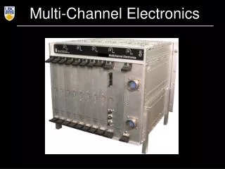
SCUBA-2 Systems Review Multi-Channel Electronics. Hilo, Hawaii June 19-23, 2006. MCE Overview. Each MCE reads signals from a 41 ×32 pixel sub-array. 4 readout cards (RC) that each read 8 output lines through 14-bit 50MHz ADCs.

E N D
SCUBA-2 Systems ReviewMulti-Channel Electronics Hilo, Hawaii June 19-23, 2006
MCE Overview • Each MCE reads signals from a 41×32 pixel sub-array. • 4 readout cards (RC) that each read 8 output lines through 14-bit 50MHz ADCs. • One address card (AC) that asserts each of 41 addresses at ~850kHz. • One clock card (CC) that interprets the commands and synchronizes all the cards.
Commands ? get_Status go enable DV-outputs st disable DV-outputs rt RTS mode (external DV supplied) fn n set frame num. to n fr n set free-run counter to n < 4095 nr n set num. of rows to n < 63 rl n set row_len to n < 4095 re reset ps power status dpa disable power for all 8 MCEs dpun disable power for MCE(n) Status Mancho_Enable = ON DV_Mode = FRUN_DV FRUN_COUNT = 47 row_len = 64 num_row = 41 ACDCCU_onoff = 0X00 Synchronizer Box
Output of Synchronizer to MCE 39 33 1 0 Fr. No. DV sync
- Cold Electronics Warm Electronics (MCE) TES Bias BC2 data_mode 2:filtered 14b 2n SQ1_FB D/A LPF SA_BIAS 2m data_mode 1:feedback 15 kΩ PID (110 Ω) 14b data_mode 0: error SQ1 + A/D A=195 Dout - SQ2 ADC_OFFSET RCn 0.1 Ω data_mode 3: raw SA_OFFSET RCn (110 Ω) SA_FB BC1 SQ2_BIAS (SB) BC3 SQ2_FB BC2 SQ1_BIAS (RS) AC
Squid CharacterizationUsing MCE • Sweep the feedback current of each stage across its full range and adjust the lower-stage feedback to keep the series-array output voltage constant. • Sweep Series-Array(SA) feedback • Choose SA_BIAS, target voltage • Sweep SQ2 feedback and adjust SA feedback • Choose SQ2_BIAS, SA_FB • Sweep SQ1 feedback and adjust SQ2 feedback • Choose SQ1_BIAS, SQ2_FB, SQ1_FB • Turn on the servo loop • Sweep through TES_bias
bias and feedback for SQ1 and SQ2 are set to 0 • Curves are near Icmax for all 8 channels • Choose points at Maximum dVout/DIin
Squid characterization Using MCE • Linux shell scripts that call C functions to issue commands to MCE • Areas of improvement: • Implementation in C • RTL PC reliability: • More reliable PCI card with additional diagnosis features • More robust Operating System: e.g., Fedora • Modular architecture (e.g., PCI Card driver independent of DRAMA and DAS)
Science Data Mode • In normal data mode the first-stage squid feedback signal, which is read at 20 kHz, is low-pass filtered and reported at every data valid pulse (DV), approximately at 200 Hz. • The filter is a 4-pole Butterworth filter with a cutoff frequency of ~50 Hz. • For each DV pulse, the MCE reports 4184 32-bit values plus a header.
Engineering Readout Modes In addition to ‘Science Data Mode’ we have a number of readout modes to help diagnose performance. • Internal DV pulses up to 1.4 kHz. Normal format. • Combined Feedback and Error signals in 32b words • 41×8 pixels sampled at 50 MHz, in a burst. • Reduced array area at a rate > 1.4 kHz • Error Signals only (ie not the Feedback signal) Combinations of these options are possible. Question: Can the Data Pipeline handle any of these?
MCE Power Shutdown MCE shuts itself down only if: • Unacceptable high voltages/currents are detected. • Unacceptable high temperatures inside the MCE are detected. MCE status prior to auto-shutdown is recorded into an EEPROM. AC/DC unit shuts down if over temperature is detected.