Download
1 / 15

E N D
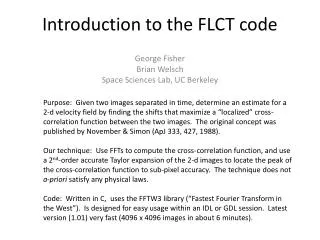
Introduction to the FLCT code Purpose: Given two images separated in time, determine an estimate for a 2-d velocity field by finding the shifts that maximize a “localized” cross-correlation function between the two images. The original concept was published by November & Simon (ApJ 333, 427, 1988). Our technique: Use FFTs to compute the cross-correlation function, and use a 2nd-order accurate Taylor expansion of the 2-d images to locate the peak of the cross-correlation function to sub-pixel accuracy. The technique does not a-priori satisfy any physical laws. Code: Written in C, uses the FFTW3 library (“Fastest Fourier Transform in the West”). Is designed for easy usage within an IDL or GDL session. Latest version (1.01) very fast (4096 x 4096 images in about 6 minutes). George Fisher Brian Welsch Space Sciences Lab, UC Berkeley
vx f1 f2 vy
Vx (inverted) f1 FLCT f2 Vy (inverted)
Comparison of original versus inverted vx velocity component using FLCT:
What is the mathematical approach used by FLCT? To construct a 2D velocity field that connects two images I1(x,y) and I2(x,y) taken at two different times t1 and t2, one must start from some given location within both images, compute a velocity vector, and then repeat the calculation while varying that location over all pixel positions. Something must be done to enhance the importance of those parts of the two images that are near the selected pixel, and to de-emphasize the parts of the image that are far away from it. FLCT does this localization by multiplying each of the two images by a gaussian of width σ, centered at pixel location (xi ,yj). We denote the resulting images as “sub-images” S1 and S2. The expressions for S1 and S2 are: The quantity σ is a free parameter in FLCT, and its optimal value changes depending on the nature of the image and the size scales present in the velocity field, as illustrated later in this poster.
What is the mathematical approach used by FLCT? (cont’d) The cross-correlation function of sub-image 1 with sub-image 2 is defined by We want to find, for each pair of sub-images S1 and S2 centered at position xi,yj, the shifts δx and δy that maximize C(δx,δy). The amplitude of the shifts, divided by the time δt =t2-t1 between images 1 and 2 defines the velocity determined by FLCT: vx=δx/δt, and vy=δy/δt. FLCT uses the convolution theorem to compute C(δx,δy) using Fourier transforms. If we write F(S1)= s1(kx,ky) and, F(S2) = s2(kx,ky), where F denotes Fourier transform, then the above equation can be written where F-1 denotes the inverse Fourier Transform. The name “FLCT” stems from this approach: Fourier Local Correlation Tracking.
Find the peak of C(δx,δy): As a practical matter, we find the peak of f(δx,δy) ≡ |C(δx,δy)|, rather than C(δx,δy) so that the operation doesn’t involve complex arithmetic. For notational simplicity, we henceforth use x,y for δx,δy in the following discussion. We employ a curve-fitting approach to find the peak in f(x,y) that was inspired by that of Chae (2004, LCT code written in IDL). First, since the images and sub-images are computed at discrete points in space, we first identify the pixel coordinates (xm,yn) of the largest value of f, denoting the largest value of f as f(xm,yn). Note that (xm,yn) may not be equal to (xi,yj), if the location of the peak of f(x,y) has shifted by more than a pixel in x or y. To find the peak to sub-pixel resolution, we then Taylor-expand f(x,y) to 2nd order about the (xm,yn) location, denoting the expansion as ft(x,y): where the partial deriviatives are evaluated at the point (xm,yn).
Find the peak of C(δx,δy) (cont’d): At the peak, we require that the x and y partial derivatives of the Taylor expanded function ft(x,y)be 0. These conditions result in a pair of linear equations which allow us to solve for the location (xmax,ymax) of the peak: To evaluate the partial derivatives, we use standard 2nd order finite difference expressions assuming a uniform grid in the sub-images: The total shift in x,y that corresponds to the peak in f is then given by δx=(xm-xi)+(xmax-xm), and δy=(yn-yj)+(ymax-yn). Equations (5) and (6) thus provide a simple and accurate method for finding the peak of the cross-correlation function to sub-pixel resolution.
Summary of the FLCT computational task: • Given 2 images I1 and I2 taken at times t1 and t2=t1+δt: First, pick a value of σ, based on image properties and any a-priori knowledge of velocity properties • Then, for each pixel location in I1 and I2, repeat until done: • Compute sub-images S1 and S2. • Compute Fourier transforms of S1 and S2, s1 and s2. • Compute inverse Fourier transform of s1*s2. This is Ci,j. • Compute the absolute value of Ci,j, |Ci,j|. • Compute the shifts δx, δy that maximize |Ci,j|. • Compute velocities vx=δx/δt, vy=δy/δt. • Move to next pixel.
Overview of FLCT code: The FLCT code, which is currently called flct, was initially written in IDL, but has since been re-written in C for portability and speed. FLCT also uses its own endian-independent binary input format for the images and for the output velocity arrays. FLCT uses the FFTW library (version 3) for computing the Fast-Fourier Transforms needed to compute the cross-correlation functions. We have written IDL procedures which write the two images flct needs into an input file, and which read the flct output file, consisting of arrays of vx,vy, and a mask array, vm. flct was designed to be easy to run from within an IDL session. To compile the FLCT code, the only external library needed is the FFTW3 library. To download a copy of the FLCT source code and compilation instructions, along with IDL i/o procedures, and pre-compiled binary executables for Linux (x86 and x86_64), Solaris, MS Windows, and OSX) go to http://solarmuri.ssl.berkeley.edu/overview/publicdownloads/software.html . Be sure to get the C version (not IDL version), and get version 1.01 or later.
Important Tangent: Accurate shifting and warping Performing quantitative tests of correlation-tracking algorithms requires the ability to shift image data with sub-pixel resolution very accurately. Here, we outline the technique we have adopted for doing this. How does one evaluate a function f(x,y) at points x,y that are slightly shifted from the points on which the data are sampled? Our approach is to note that the problem can be written as a convolution between the original function f(x,y) and a delta function: Recognizing this, one can use the convolution theorem to write this equation in Fourier space: where
Uniform Shifts to sub-pixel accuracy: If δx, δy are the same values for the entire image, i.e. a uniform shift, then one can perform a simple inverse FFT to compute values for the shifted image: This shifting technique is very fast – just a few seconds for 40962 images. δx=50.75 δy=-100.25
Nonuniform shifts (warping): If δx,δy are themselves functions of image location, then one cannot find the warped image values with a simple inverse FFT, because the Fourier transform of the needed delta function is different for each point in the image. However, one can still write down the solution in closed form: The double sum must be performed for each spatial point of the image. This is very accurate, but for images larger than roughly 5122, is quite slow for typical contemporary processors. Why do these FFT-based techniques shift and warp images more accurately than techniques based on the usage of more conventional (e.g. cubic convolution or B-spline) interpolation methods? The answer appears to lie in the destruction of phase relationships between small and large-scales in the interpolation techniques that focus on local behavior near a point.
Comparison of FLCT inversions using shifts with cubic convolution and our FFT-based warping technique Warp:
IDL and C-based code to perform accurate shifts and warping is publicly available • In IDL, the function shift_frac2d.pro is provided as a part of the FLCT software, and uses the same syntax as the shift function in IDL: f2=shift_frac2d(f1,delx,dely). It will perform uniform shifts or warping depending on the rank of delx and dely. • In C, we have written functions shift_frac2d and warp_frac2d which are much faster than the IDL function. The code will be publicly posted, and is currently available upon request (and has already been given to the HMI team).