Download
1 / 118
1.71k likes | 2.84k Views
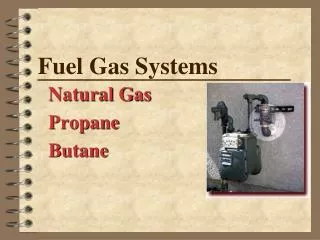
ASPE/ASSE Meeting February 10, 2010 Cleveland, OH. Fuel Gas Systems. Natural Gas Propane Butane. By: Ron George, CPD, President President, Ron George Design & Consulting Services 3525 N. Dixie Hwy., Monroe, MI Monroe, Michigan 48162 Ph: (734) 322-0225 Cell: (734) 755-1908.

E N D
ASPE/ASSE Meeting February 10, 2010 Cleveland, OH Fuel Gas Systems Natural Gas Propane Butane By: Ron George, CPD, President President, Ron George Design & Consulting Services 3525 N. Dixie Hwy., Monroe, MI Monroe, Michigan 48162 Ph: (734) 322-0225 Cell: (734) 755-1908
Fuel Gas Codes & Standards • Mechanical Codes covering Fuel Gasses: • BOCA - Basic Mechanical Code (no longer updated in favor of The International Codes) • IAPMO - Uniform Plumbing Code (UPC) (Coordinated with NFPA 54) • IMC - International Mechanical Code (Prior to 2000) • IFGC - International Fuel Gas Code (Fuel gas sections from IMC were used to develop IFGC in 2000. • Standards/Organizations dealing with Fuel Gas: • AGA - American Gas Association • NFPA 54 - National Fire Protection Association • CSA - Canadian Standards Association • ASME - Power & Process Piping Standards
How do I Size Gas Piping? • Determine the heating and equipment loads in BTU’s, convert to CFH and size the piping based on acceptable pressure drops using the appropriate code approved pipe material. BTU/H CFH Distance Pipe Size Chart Equipment Label
What does BTU stand for? • BTU stands for “British Thermal Unit”. • A British Thermal Unit is the amount of heat required to raise one pound of water one degree Fahrenheit.
British Thermal Unit (BTU) One pound of waterwill increase by 1 degree F when 1 BTU is added. Example: One pound of 60 degree F water plus 1 BTU = one pound of 61 degrees Fwater. 1 pound of 60 degree water 1 BTU 1 pound of 61 degree water
What is CFH? • CFH is an industry term used to describe the quantity of gas in Cubic Feet delivered during a specified time period. (Usually 1 hour) • So CFH stands for Cubic Feet per Hour. • 1 Cubic foot of gas = 1000 BTUs + - (950-1100 BTUs/CF depending on the supplier)
Natural Gas Properties 1 Cubic Foot of Natural Gas = 1,000 BTU’s • Heat of combustion is measured in BTU’s/cu.ft. Natural Gas = 1,000 BTU’s/CF (Caloric Value) • Specific Gravity of Nat. Gas = .60 - .65(Air =1.00) • Natural Gas is Lighter than air. (It will dissipate) • Flammability Limits (% Volume in air) • Lower = 3.9%, <<<<< Flame >>>>> Upper = 15.0% Below 3.9% too lean for Combustion 9-10% = Good Above 15% too rich for combustion • Combustion air requirements in Cubic Feet: • Per cu. foot of Natural Gas = 10 cubic feet of air. • Per 100 BTU’s = 1 cubic foot of air.
Fuel Gas Properties Table: Odor Additives Source: NFPA 54 Handbook
Fuel Gas is Explosive! On May 19, 2008 a natural gas leak caused an explosion that injured 14 construction workers and damaged four floors on the unfinished hotel.
Fuel Gas is Explosive! New Braunfels, TX. 1 dead, 1 seriously burned.
Natural Gas Distribution Pressures • Three Pressure Classifications • High Pressure (1,000’s PSI to 100’s) • Medium Pressure (5 PSI to 100’s PSI) • Low Pressure (Less Than 5 PSI) High Pressure gas is in typically only utilized in utility distribution lines, so most plumbing engineers will deal with only Medium or Low Pressure Gas
Natural Gas High Pressure • High Pressure - 1,000’s to 100’s PSI • Transmission mains from pumping stations to Local utility distribution mains. • Typically High Pressures are utilized over long distances to reduce pipe sizes. Pumping Station Medium press. 60 psi +- PRV PRV Well Low press. High press. 900 psi+- Energy Company lines 1/2 psi +-
Natural Gas Medium Pressure • Medium Pressure • Local Utility Distribution • Large Industrial users. • Typically 5psi to 100’s of PSI Local Gas Utility Co. Distribution lines Pumping Station Medium press. 60 psi +- PRV PRV Low press. High press. 900 psi +- Well 1/2 psi +-
Natural Gas Low Pressure • Low Pressure • Commonly used inside buildings • Commercial and residential users. • Typically less than 5 PSI (code requirement indoors) Pumping Station Medium press. 60 psi +- PRV furnace PRV Low press. High press. 900 psi +- 1/2 psi + - Homeowner Responsibility
Fuel GasPressure Conversions Gas pressures in buildings are often given in Pounds, Ounces or Inches. Make sure you convert to the proper units for sizing. Often a manufacturer refers to equipment pressure in inches or ounces of pressure because it is a more accurate measurement. • 1 PSI = 2.31 feet of head = 28 inches of Water Column (WC) • 1 PSI = 16 Ounces =28 Inches =2.31 feet of head • 1/2 PSI = 8 Ounces = 14 Inches WC =1.16 feet of head • 1/3 PSI = 6 Ounces = 10 Inches WC =.77 feet of head • 1/4 PSI = 4 Ounces = 7 Inches WC =.58 feet of head Gas Pressure Conversion Chart
How Do we Change from a High Pressure to a Low Pressure? • Pressure Regulators.
Gas Regulator Operation 60 PSI ½ PSI 1/2 PSI
Odor Added to Fuel Gas Odor is added by most gas companies so leaks can be detected. The physical properties of natural gas include color, odor, and flammability. The principal ingredient of gas is methane, which is colorless, odorless, and highly flammable. Some of the associated gases in natural gas include Mercaptin, a hydrogen sulfide additive, it has a distinct and penetrating sulfur or Rotten Egg odor, and a few parts per million is sufficient to impart a decided odor in the gas. A Volcanic Problem - The engineers for the Mirage Casino in Las Vegas needed to use Natural Gas to enhance the special effects for the volcano eruption in front of the casino. The concern was prior to eruption a distinctive odor of of Natural Gas or the sulfury Rotten Egg smell would be noticeable to the crowds if gas with Mercaptin was used. The officials insisted on having some kind of odorso they could detect a gas leak. The engineers designed a scrubber to remove the Mercaptin odor and replace it with a Pina’ Colada odor.
Natural Gas Pipe Material • Cast IronNot recommended/allowed on fuel gas piping systems. Older cities used CI (½ PSI limit) • Black Steel (Schedule 40) ASME B36.10, 10M or ASTM A53 or ASTM A106 • Polyethylene (PE) Underground outside building where approved) • Stainless Steel (CSST) ANSI/AGA LC 1. • Copper (Not recommended if gas is more than 0.3 Grains of Hydrogen Sulfide/100 CF) Often used as semi rigid tubing for appliance connections. • Aluminum ASTM B241 (Alum. Alloy 5456 is Prohibited) • (All piping material selections should meet the local code’s approved materials list.) Pumping Station Copper or Polyethylene or CSST wrapped & coated Black Steel U.G. PRV furnace PRV Black Steel/CSST PE or asphalt wrapped Sch 80 - 160 Black steel W/ Cathodic Protection (Pressure often dictates material) Abv. ground
Corrugated Stainless Steel Tubing (CSST) • CSST has made residential and light commercial gas-distribution much easier. Black steel pipe is still preferred for mains and trunks to manifolds. From the manifold the branch piping can be installed with ease. • CSST is lightweight and flexible and will cut down on installation time up to 50%.
Underground Gas Piping Installations Clearances - Far enough from U.G. structures to avoid contact and provide protection against damage. U.G. plastic piping shall be clear of or insulated from heat sources. (U.G. Steam mains, Htg HW pipes Etc.) Protection Against Damage - Unstable soil, Foundation Walls, Heavy vehicles: Provide sufficient depth of cover or a pipe sleeve. When gas piping is buried in planting areas, bury piping sufficiently below cultivating depth. Warning Tape/Wire - Always put a tracer wire with plastic piping and bury “WARNING BURIED GAS LINE” tape in trench above all gas piping to warn excavators of pipe below.
Protection Against Damage • Provide sufficient depth of cover or a pipe sleeve where there is unstable soil, a foundation wall penetration or heavy vehicle traffic. • When gas piping is buried in planting areas, bury piping sufficiently below cultivating depth. G
Warning Tape/Tracer Wire • Engineers should always require a tracer wire when using plastic piping to allow pipe locators to find the pipes. • Also specify warning tape that states: “WARNING BURIED GAS LINE BELOW”. The tape should be in the trench at least 12 inches above the gas piping to warn excavators of the gas pipe below Warning Tape Tracer Wire (In trench above plastic pipe) (In trench 12”above pipe) Caution - Buried Gas Line Caution - Buried Gas Line Buried Gas Line
Underground Gas Piping Installations Cover Depth - Should be installed with at least 18 inches of cover. Can be 12 inches in areas where external damage is not likely. If less than 12 inches provide a protective conduit or bridging. Always use warning tape. & tracer wire for plastic piping. Backfilling Trenches - Pipe should have a firm, continuos bearing on trench bottom. When installing gas piping, especially plastic, in a flooded trench care should be exercised to prevent the pipe from floating up in the trench during backfilling operations. Caution Tape Tracer Wire (for plastic pipe) Continuous pipe bedding Gas Pipe
Underground Gas Piping Installations Protect Against Corrosion - Ferrous metal piping that is in contact with earth should be protected from corrosion by asphalt coating and wrapping piping below grade. Protect Against Freezing - If the fuel gas supplier indicates, hydrates or moisture is high, the gas piping should be protected from freezing. Freezing of water in drip legs or low points in the piping can split piping and lead to gas leaks and possibly and explosion or fire. Locate Gas line below frost line or in a heated space. If Gas line is subject to freezing provide heat tracing and Insulation. Wet gas condenses water to this point Freezing can crack pipe allowing gas to leak out of pipe Boom
Dirt Leg (For Dry Gas) Clean Gas Sediment falls Source: NFPA 54 Handbook
Emergency Gas Shut-off Valve (Earthquake valve) • Some seismic areas of the country require an Emergency Gas shut-off valve that automatically closes when there is an earthquake. • The Earthquake Valve Industry has emerged because of the recent earthquakes and ensuing fires that have struck California and other parts of the world. Designers, Building Officials and Utility companies have become aware of the need for Earth Quake Valves (EQVs) after experiencing and viewing these disasters. Source: Safe-T-Quake Co.
Gas Pipe through Foundation Wall Below Grade not allowed in most areas! Piping through foundation walls below grade should have a sleeve with the annular space sealed from the building. Gas Meter/ Regulator M Void space Sealed sleeve Expansive or Clay Soil Foundation Wall Gas Pipe Section at Foundation Wall End view U.G. Pipe
Gas Pipe Should enter Building above Grade! Piping walls should have a sleeve sealed from inside the building. Sealed sleeve Gas Meter/ Regulator M Foundation Wall Section at Foundation Wall
Bonding of CSST Gas Pipe Inside Buildings • Proper bonding and grounding of Corrugated Stainless Steel Tubing (CSST) systems may reduce the risk of damage and fire from a lightning strike. Lightning is a highly destructive force. Even a nearby lightning strike that does not strike a structure directly can cause systems in the structure to become electrically energized. Differences in potential between systems may cause the charge to arc between systems. • Such arcing can cause damage to CSST, including blowing holes that can leak flammable gasses. • Bonding and grounding should reduce the risk of arcing and related damage. • Arcing from lightning strikes has been known to blow holes in un grounded CSST fuel gas lines causing Gas leaks and Fires. • The building owner should confirm that a qualified contractor has properly bonded the CSST gas system to the grounding electrode system of the premises. Refer to the manufacturers installation manual for bonding and grounding instructions for CSST. • (Section 4.10 Electrical Bonding/Grounding in the Gastite Design & Installation Guide for details on bonding & grounding CSST.)
Lightning Protection Systems for CSST Piping • All ownersshould consult a lightning safety consultant to determine whether installation of a lightning protection system would be required to achieve sufficient protection for all building components from lightning. Factors to consider include whether the area is prone to lightning. Areas with high lightning risk include but are not limited to: Alabama, Arkansas, Florida, Georgia, Illinois, Indiana, Iowa, Kentucky, Louisiana, Maryland, Michigan, Mississippi, Missouri, New Mexico, North Carolina, Ohio, Oklahoma, Pennsylvania, South Carolina, Tennessee, Texas, Virginia and West Virginia. • One currently available source of information regarding areas more prone to lighting than others is the flash density map provided by the National Weather Service which can be found at http://www.lightningsafety.noaa.gov/lightning_map.htm. • Lightning protection systems are beyond the scope of this presentation and the manufacturers installation guidelines, and are covered by National Fire Protection Association, NFPA 780, the Standard for the Installation of Lightning Protection Systems, and other standards.
Dielectric Connections in all Gas Pipes • The owner should confirm with the local gas supply utility company that a suitable dielectric union is installed at the service entry of the structure between underground metallic piping and the gas pipes going into the building as required by code.
National Electrical Code • National Electric Code (NEC), Section 250.104b, states that “bonding all piping and metal air ducts within the premises will provide additional safety”. Manufacturer’s recommend that all continuous metallic systems be bonded and grounded. The owner should confirm with an electrical or construction specialist that each continuous metallic system in a structure has been bonded and grounded by an electrical professional in accordance with local building codes. This should include, but is not limited to metallic chimney liners, metallic appliance vents, metallic ducting and piping, electrical cables, and structural steel.
Separation of Fuel Gas Pipe from Electrically conductive systems. • Care should be taken when installing any type of fuel gas piping (including CSST, iron, or copper) to maintain as much separation as reasonably possible from other electrically conductive systems in the building. Refer to the manufacturers’ Installation Manual. (Gastite D&I Guide sec. 4.3 Routing, for installation techniques.) Consult local building codes as to the required separations for CSST from such conductive systems including metallic chimney liners, metallic appliance vents, metallic ducting and piping, and electrical cables. See for instance the Indiana Residential Code, section 675 IAC 14-4.3-155.5 Section G2411.1; gas pipe bonding.
Local Building Codes Have Jurisdiction • Local building codes have jurisdiction, however, as a general practice, fuel gas piping, including CSST, should not be installed within a chase or enclosure that houses a metallic chimney liner or appliance vent that protrudes through the roof. In the event such an installation is necessary and conforms to local building codes, the metallic chimney liner or vent must be bonded and grounded by a qualified electrical professional, and a separation distance, as specifically permitted by the applicable local building code between the CSST and the metallic chimney liner or vent, is required. Physical contact between CSST and the metallic chimney liner and/or vent is prohibited. If this physical separation cannot be specifically identified in the local building code and achieved or any local building code requirements cannot be met along the entire length, then rerouting of the CSST is required unless such installation is specifically permitted by the local building inspector.
2009 National Fuel Gas Code Update • As of October 2008 – the National Fuel Gas Code requires bonding of ALL CSST systems per section 7.13 – Electrical Bonding and Grounding.
Hybrid Multi-Unit Condo Building CSST Branches Steel Riser
Hybrid System w/ Local Gas Regulator and CSST (4) 50,000 BTU/H 5 PSI CAP. IP OP 1/4 PSI
Gas Pipe Inside Buildings Gas Piping Prohibited Locations: In Circulating Air Duct Through Circulating Air Duct Clothes chutes In Chimney In Gas Vent In Ventilation duct In Dumb Waiter In Elevator Shaft Boom Leaks in concealed locations can allow explosive gasses to accumulate unnoticed
Gas Pipe Inside Buildings Gas Piping in concealed Locations: Should have a casing or chase for solid walls No unions, valves or joints in concealed spaces No compression couplings No Bushings No swing joins made by multiple fittings Exceptions: Brazed Tubing Fittings listed for concealed locations Boom Leaks in concealed locations can allow explosive gasses to accumulate unnoticed
How Do You Test For A Gas Leak? • With a Match? No • With Soap? Sometimes (Must be non-corrosive) • With a Gas Detector? Yes