Download
1 / 31
320 likes | 423 Views
SPX High Level RF and RF Interlock Systems WBS U1.03.03.01. Doug Horan RF Systems Engineer Accelerator Systems Division/RF Group DOE Lehman CD-2 Review of APS-Upgrade 4-6 Decem ber 2012. Outline. The HLRF Team HLRF System WBS Scope Requirements Design Interfaces Risks Considered R&D

E N D
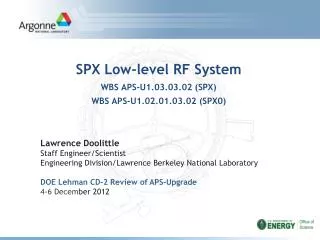
SPX High Level RFandRF Interlock SystemsWBS U1.03.03.01 Doug Horan RF Systems Engineer Accelerator Systems Division/RF Group DOE Lehman CD-2 Review of APS-Upgrade4-6 December 2012
Outline • The HLRF Team • HLRF System WBS Scope • Requirements • Design • Interfaces • Risks Considered • R&D • ES&H • Cost • Schedule DOE Lehman CD-2 Review of the APS Upgrade Project 4-6 December 2012
HLRF Scope / Cost SummaryWBS U1.03.03.01 • Design, construction, installation, and commissioning of eight 2.815GHz/10kW cw high-level klystron rf amplifier systems, including waveguide transmission systems, interlock systems, and two high voltage power supplies • Interlock systems include: → SPXrf equipment protection → Personnel safety → Interface to Access Control Interlock System (ACIS) → Interface to Machine Protection System (MPS) DOE Lehman CD-2 Review of the APS Upgrade Project 4-6 December 2012
HLRF System Requirements – WBS U1.03.03.01 • Produce and deliver approximately 8kW cw rf power to each cavity input waveguide flange • Provide rf interlock functions, including rf hardware protection and personnel protection • Maintain minimum contribution to rf system integrated noise DOE Lehman CD-2 Review of the APS Upgrade Project 4-6 December 2012
HLRF Org Chart High-Power RF D. Horan RF Interlocks D. Horan R. Agner Interlock Engineer • Amplifier Systems • D. Horan • Grelick • M. Middendorf • R. Agner • Tech 3 • HLRF Engineer RF Systems Installation D. Bromberek T. Smith D. Jefferson Tech 4 RF Test Stands M. Middendorf T. Smith M. Douell T. Jonasson Electronics D&D Electrical System G. Doktorczyk New Hire DOE Lehman CD-2 Review of the APS Upgrade Project 4-6 December 2012
HLRF System Scope – WBS U1.03.03.01 • Design, construction, installation, and commissioning of eight 2.815GHz/10kW cw high-level klystron rf amplifier systems, including the following subsystems: → Eight waveguide transmission systems → Interlock systems → Two high voltage power supplies • Interlock systems include: → SPX rf equipment protection → Personnel safety → Interface to Access Control Interlock System (ACIS) → Interface to Machine Protection System (MPS) DOE Lehman CD-2 Review of the APS Upgrade Project 4-6 December 2012
HLRF System Design -- WBS U1.03.03.01 • 10kW klystron amplifiers, one per cavity • Common HVPS at each sector • HVPS units fed from common 480V source for correlated noise • Master HVPS switching clock to interleave and reduce HVPS ripple DOE Lehman CD-2 Review of the APS Upgrade Project 4-6 December 2012
HLRF Waveguide System Design -- WBS U1.03.03.01.02 10kW AMPLIFIERS • Waveguide is WR284 aluminum – pressurized with nitrogen to 5 psi • 10kW amplifiers are positioned on equipment mezzanine in Building 400A1 (Sector 5) and Building 400A4 (Sector 7) • Waveguide system losses estimated at ≈ 1dB → Approximately 8kW available at each cavity input flange WAVEGUIDES AND PENETRATION INTO SR TUNNEL PRELIMINARY DESIGN OF HLRF INSTALLATION IN BUILDING 400A1 AND STORAGE RING SECTOR 5 DOE Lehman CD-2 Review of the APS Upgrade Project 4-6 December 2012
HLRF System Design – RF Interlocks WBS U1.03.03.01.04 → Fast RF IL WBS U1.03.03.01.07 → ACIS/RF InterfaceWBS U1.03.03.01.04 → Slow RF IL • Master slow and fast interlock systems in amplifier systems • Slave slow and fast interlock systems at cryomodule location • Slave fault outputs drive external inputs of respective master • Slow interlock is PLC-based → ≈ 20ms response time • Fast interlock is electronic → ≈ 10μsec response time • Interlocks can trigger fast cavity detuning or beam dump to protect hardware • ACIS/RF Interface disables rf systems for tunnel access DOE Lehman CD-2 Review of the APS Upgrade Project 4-6 December 2012
HLRF System Design – Personnel SafetyWBS U1.03.03.01.06 • SPX waveguide nitrogen pressure is monitored to detect the potential for rf radiation leakage – Low pressure indicates the potential for rf leakage → Affected SPX rf systems are shut down → All Storage Ring and Booster rf systems are shut down • High voltage behind bolted panels with interlock switches STORAGE RING AND BOOSTER RF SHUTDOWN DOE Lehman CD-2 Review of the APS Upgrade Project 4-6 December 2012
HLRF Interfaces WBS U1.03.03.01 • LLRF • Interlock system input signals -- TC’s, RTD’s, flowmeters, thermal diodes, vacuum instrumentation • Storage Ring MPS System • Cavity input waveguide flange • DI water • AC Power • Storage Ring Access Control Interlock System -- ACIS/SI • Existing 352-MHz RF Waveguide Air Interlock System • APS computer network DOE Lehman CD-2 Review of the APS Upgrade Project 4-6 December 2012
HLRF System Risks WBS U1.03.03.01 • Availability of a reliable and stable klystron → The klystrons will be a new design that will require testing and evaluation • On-time klystron delivery Mitigation: -- Plan Advanced Procurement for first-article 10kW klystron -- Extensive testing and evaluation of first article DOE Lehman CD-2 Review of the APS Upgrade Project 4-6 December 2012
HLRF R&D – SPX0 -- WBS U1.02.01.03.01 • Design, construction, installation, and commissioning of two 2.815GHz/5kW cw high-level klystron rf amplifier systems, including waveguide transmission systems, high-voltage power supplies, and interlock systems • Interlock systems include: → SPX0 rf equipment protection → Personnel safety → Interface to storage ring tunnel Access Control Interlock System (ACIS) → Interface to storage ring Machine Protection System (MPS) SPX0 HLRF INSTALLATION IN BUILDING 400A1 AND STORAGE RING SECTOR 5 FIRST SPX0 5kW KLYSTRON AMPLIFIER DOE Lehman CD-2 Review of the APS Upgrade Project 4-6 December 2012
HLRF R&D – Test Stands -- WBS U1.02.01.03.10 • Vertical cavity tests at ATLAS • Building 400A RF Test Stand → RF power tests on dampers, loads, and windows • 5kW Horizontal Cavity and Tuner Test at ATLAS → Utilizes first 5kW SPX0 amplifier → Scheduled for December 2012 • 5kW cryomodule tests at JLab → Utilizes first 5kW SPX0 amplifier HOM DAMPER RF POWER TEST IN 400A 2.815GHz/4kW CW AMPLIFIER IN 400A FIRST SPX0 5kW KLYSTRON AMPLIFIER INSTALLED AT ATLAS DOE Lehman CD-2 Review of the APS Upgrade Project 4-6 December 2012
HLRF System ES&H WBS U1.03.03.01 • Integrated Safety Management System (ISMS) • APS-U Project following Argonne’s ISMS program requirements • Argonne Integrated Safety Management System (ISMS) Description recently revised and submitted to DOE ASO • Describes framework for integrating ESH requirements with mission objectives • References Argonne LMS procedures which implement specific portions of the ISMS • Identify General Safeguards and Security Requirements • Note special materials or project specific security requirements • APS-U Project required to follow Argonne’s Operations Security Program (OPSEC) Master Plan • Identify General Safety Requirements to Specific WBS Level • Electrical safety → high voltage • Ionizing radiation → X-ray emission from klystron and rf cavities • RF radiation safety → rf leakage from waveguide transmission system • All equipment not rated by a nationally-recognized testing laboratory (NRTL) will be inspected by qualified electrical equipment inspectors DOE Lehman CD-2 Review of the APS Upgrade Project 4-6 December 2012
SPX High Level Radio Frequency Scope and WBSU1.02.01.03 & U1.03.03 DOE Lehman CD-2 Review of the APS Upgrade Project 4-6 December 2012
SPX High Level Radio Frequency Scope and WBSU1.02.01.03 & U1.03.03 DOE Lehman CD-2 Review of the APS Upgrade Project 4-6 December 2012
SPX High Level Radio Frequency Obligation Profile U1.02.01.03 & U1.03.03 DOE Lehman CD-2 Review of the APS Upgrade Project 4-6 December 2012
SPX High Level Radio Frequency BOE Contingency U1.02.01.03 & U1.03.03 DOE Lehman CD-2 Review of the APS Upgrade Project 4-6 December 2012
HLRF Cost Drivers • SPX0 R&D → 5kW klystrons¹ (2) → 30kW High voltage power supplies¹ (2) → 50kW isolators¹ (2) → Waveguide systems ¹ Internal component of 5kW amplifier • SPX → Klystrons² (8) → 150kW high voltage power supplies (2) → 50kW isolators² (8) → Waveguide, including HOM filters (8) ² Internal component of 10kW amplifier DOE Lehman CD-2 Review of the APS Upgrade Project 4-6 December 2012
SPX R&D and Production MilestonesU1.02.01.03 & U1.03.03 DOE Lehman CD-2 Review of the APS Upgrade Project 4-6 December 2012
SPX High Level Radio Frequency Milestones U1.02.01.03 & U1.03.03 DOE Lehman CD-2 Review of the APS Upgrade Project 4-6 December 2012
SPX High Level Radio Frequency Summary Schedule U1.02.01.03 & U1.03.03 DOE Lehman CD-2 Review of the APS Upgrade Project 4-6 December 2012
HLRF Work After CD-2 • 1.02 R&D: Complete design of 10kW amplifier systems, waveguide transmission systems, and rf interlock systems • Hold design reviews for each subsystem • 1.03: Begin procurement of hardware for amplifiers and sub-systems • Begin procurement of high voltage power supplies • Select and procure klystrons DOE Lehman CD-2 Review of the APS Upgrade Project 4-6 December 2012
HLRF Summary WBS U1.03.03.01 • ▪ Design, construction, installation, and commissioning of: • →Eight 2.815GHz/10kW cw klystron rf amplifiers • → Waveguide transmission systems • → Personnel safety and equipment interlock systems • → Two high voltage power supplies • ▪The system traces back to the higher level requirement of: • →Providing the rf power necessary for the SPX cavities to develop full deflecting field • →Protect SPX rf system hardware from damage due to overpower or arcing • → Provide personnel protection against rf radiation, x-ray, and high-voltage hazards • ▪The conceptual design fulfills basic system topology requirements • ▪ The total cost is $7,823k • ▪We are ready to proceed with final design of the system • ▪HLRF installation and checkout: • → SPX0 R&D HLRF System – Completed in September 2014 • → SPX HLRF System – Completed in December 2018 DOE Lehman CD-2 Review of the APS Upgrade Project 4-6 December 2012
HLRF Backup Slides Follow DOE Lehman CD-2 Review of the APS Upgrade Project 4-6 December 2012
SPX0 R&D HLRF Installation and Checkout DOE Lehman CD-2 Review of the APS Upgrade Project 4-6 December 2012
SPX HLRF Installation and Checkout DOE Lehman CD-2 Review of the APS Upgrade Project 4-6 December 2012
SPX HLRF Installation and Checkout ▪ 10kW Amplifiers and Klystrons → Preliminary electrical checkout of amplifiers → Klystrons acceptance-tested at manufacturer → Amplifiers and klystrons tested together ▪ Waveguide System → Preliminary VSWR check terminated with precision load → Test to full power into load prior to connection to cryomodule ▪ Interlock Systems → End-to-end electrical check of interlock system and related signal cables → Interlock functionality check prior to application of rf power to cryomodule ▪ HVPS → Factory test at full-load voltage and power DOE Lehman CD-2 Review of the APS Upgrade Project 4-6 December 2012
HLRF System Design -- MPS/RF Interface WBS#..... CAVITY QUENCH LLRF REFRIGERATOR FAULT CRYOGENICS INTERLOCK SYSTEM BEAM DUMP COMMAND TO STORAGE RING MPS SYSTEM LOM DAMPER RETURN TEMP & FLOW HOM 1 DAMPER • Protects SPX rf hardware from damage caused by SR beam- generated rf power: → Overpower of cavities, HOM dampers, klystron isolator/load → Cavity vacuum fault → Arcs at cavity window, HOM damper, or klystron isolator → Cavity quench → Refrigeration fault • Generates a fast cavity detune command in response to fault conditions • Beam dump command sent to storage ring MPS system if fast cavity detuning does not clear fault RETURN TEMP & FLOW (OPTICAL FIBER) HOM 2 DAMPER RETURN TEMP & FLOW SPX-0 MPS/RF INTERFACE FPC AND LOM WINDOWS (4) RETURN TEMP & FLOW CAVITY TEMP LOM DAMPER ARC DET FPC ARC DET FAST CAVITY DETUNING CAVITY WINDOW ARC DET KLYSTRON ISOLATOR PIEZO TUNER ARC DET LOM DAMPER VACUUM FAULT FPC VACUUM FAULT CAVITY VACUUM FAULT 50kW LOAD FIELD PROBE REFLECTED POWER KLYSTRON ISOLATOR POWER FLOW FROM CAVITY DOE Lehman CD-2 Review of the APS Upgrade Project 4-6 December 2012
HLRF System Design – ACIS/RF InterfaceWBS U1.03.03.01.07 • Storage Ring ACIS provides permits for SPX rf drive and high voltage power supplies • Both permits removed when personnel have access to storage ring tunnel DOE Lehman CD-2 Review of the APS Upgrade Project 4-6 December 2012