Download
1 / 100
1.03k likes | 1.29k Views
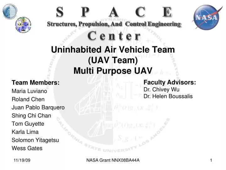
S P A C E Structures, Propulsion, And Control Engineering C e n t e r. Uninhabited Air Vehicle Team (UAV Team) Multi Purpose UAV. Faculty Advisors: Dr. Chivey Wu Dr. Helen Boussalis. Team Members: Maria Luviano Roland Chen Juan Pablo Barquero Shing Chi Chan

E N D
S P A C E Structures, Propulsion, And Control Engineering C e n t e r Uninhabited Air Vehicle Team(UAV Team)Multi Purpose UAV Faculty Advisors: Dr. Chivey Wu Dr. Helen Boussalis Team Members: Maria Luviano Roland Chen Juan Pablo Barquero Shing Chi Chan Tom Guyette Karla Lima Solomon Yitagetsu Wess Gates NASA Grant NNX08BA44A
Overview • Project requirements • Mission profile • UAV design • Computational fluid dynamics • UAV structures • Avionics • Servo bench testing • Flight control system • Trainer integration • Budget and schedule NASA Grant NNX08BA44A
Project Requirements • 3 hrs endurance • Autonomous • 10 lb payload • Cruise Altitude 3280 ft • Cruise Speed 50 mph • Gross weight 55 lbs NASA Grant NNX08BA44A
Mission Profile Cruise Out Cruise Back Climb 3280 ft Climb Descend Descend PayloadDrop Takeoff Landing 180 miles CruiseSpeed50mph NASA Grant NNX08BA44A
Aerodynamic Design NASA Grant NNX08BA44A
Tapered RectangularSwept Required wing aerodynamic characteristics Lift coefficient CL = L/q.S High lift to drag ratio CL/CD Aircraft Wing Selection NASA Grant NNX08BA44A
Tapered AR = 5 Span = 11 ft Cr = 3.55 ft Ct = 1.24 ft Cmean = 2.4 ft Wing Loading = 2.3 lbs/ft^2 Results CL = 0.0531 CL/CD = 20 Trade Study • Swept Back • AR = 5 • Span = 11 ft • Cr = 3.3 • Ct = 1.15 • Cmean = 2.2 • Wing Loading • = 2.3 lbs/ft^2 • Results • CL = 0.0607 • CL/CD = 20 • Rectangular • AR = 5 • Span = 11 ft • C = 2.2 ft • Cmean = 2.4 ft • Wing Loading • = 2.3 lbs/ft^2 Results CL = 0.0739 CL/CD = 24 NASA Grant NNX08BA44A
Calculated Lift Coefficient NASA Grant NNX08BA44A
Computational Fluid Dynamics (CFD) Why CFD Verify hand calculations Reduce wind tunnel testing cost XFLR5 Software Produces accurate aerodynamic coefficients Fast and user-friendly Wings Analyzed Swept back Rectangular Tapered NASA Grant NNX08BA44A
XFLR5 Wing Geometry Input NASA Grant NNX08BA44A
CFD Results for Swept Back Wing NASA Grant NNX08BA44A
CFD Results for Rectangular Wing NASA Grant NNX08BA44A
CFD Results for Tapered Wing NASA Grant NNX08BA44A
Swept Back WingHand Calculations vs. CFD NASA Grant NNX08BA44A
Rectangular WingHand Calculations vs. CFD NASA Grant NNX08BA44A
Tapered Wing Hand Calculations vs. CFD NASA Grant NNX08BA44A
CFD Lift Comparison NASA Grant NNX08BA44A
CFD Drag Polar NASA Grant NNX08BA44A
UAV Configuration NASA Grant NNX08BA44A
Configuration Layout NASA Grant NNX08BA44A
Aerodynamic Analysis NASA Grant NNX08BA44A
Takeoff and Landing Distance NASA Grant NNX08BA44A
Constraint Diagram NASA Grant NNX08BA44A
Structural Design & Analysis NASA Grant NNX08BA44A
Studying Aircraft Structures • Aircraft structure is required to support two distinct classes of load • Ground Load: movement on the ground ( taxing, landing, and towing) • Air Loads: loads during flight by maneuvers and gusts. • Function of structural components: • To transmit and resist loads to provide shape and protect passengers, payload, systems, etc from the environmental conditions found during flight. • Two type of structures • Semi-monocoque – shell is usually supported by members and frames to support bending, compressive loads, torsional loads without bucking. • Monocoque – thin shells that rely on the skin for their capacity to resist the loads NASA Grant NNX08BA44A
V-n Diagram • Shows flight load factors or “g forces” that are used for structural design, as a function of air speed. • Load factor “n” is the ratio between the air load acting on the airplane, to the weight of the aircraft • n = L / W • For level flight, assume n = 1 • However, during maneuvers n can be larger: • Acceleration • Turns • Climb • Gust loads NASA Grant NNX08BA44A
V-n Diagram Total air load produced = 6.20*55 = 341.0 lb NASA Grant NNX08BA44A
V-n Diagram Vc VA Vs Vd 11/19/09 NASA Grant NNX08BA44A NASA Grant NNX08BA44A 28
Wing Load Distribution • Schrenk’s method gives approx. calculations for the span wise load. • Maximum lift is generated by root chord, and minimum lift is generated by the tip cord. • Assumes the load distribution on the wing has an elliptical planform and a trapezoidal planform. Both distributions are calculated and then an average is taken: NASA Grant NNX08BA44A
Span-wise Load Distribution NASA Grant NNX08BA44A
Analysis – Wing Spar Braided carbon fiber round tube Braided carbon fiber rectangular tube σultimate = 640,000 psi http://dragonplate.com/docs/DPSpecRoundTube.pdf http://dragonplate.com/docs/DPSpecRecTube.pdf NASA Grant NNX08BA44A
Analysis – Wing Spar Round Tube Rect. Tube 11/19/09 NASA Grant NNX08BA44A NASA Grant NNX08BA44A 32
Wing Structure Spar 1 – 80 in @ approx. 15 % of cordSpar 2 – 65 in @ approx. 60 % of cordRib Separation 6 inFuel Tank(s) Fuel Tank Ribs Spar 2 Spar 1 Estimated Weight = 3.56 lbs 11/19/09 NASA Grant NNX08BA44A 33 NASA Grant NNX08BA44A
Integration of Isotruss http://www.delta7bikes.com/shop-bike.htm • Isotruss – A light, compact grid structure composed of carbon fiber and Kevlar filaments. • Uses: • Frames • Poles • Stiffeners • Beams 11/19/09 NASA Grant NNX08BA44A NASA Grant NNX08BA44A 34
Isotruss http://www.delta7bikes.com/ NASA Grant NNX08BA44A
Avionics NASA Grant NNX08BA44A
Objective NASA Grant NNX08BA44A
Requirements 360 oz-in 11/19/09 NASA Grant NNX08BA44A NASA Grant NNX08BA44A 38
Process 11/19/09 NASA Grant NNX08BA44A NASA Grant NNX08BA44A 39
Results & Integration NASA Grant NNX08BA44A
Control Surfaces Tom Guyette November 19, 2009 NASA Grant NNX08BA44A 41
Forces on Control Surfaces Dynamic pressure q from conservation of momentum Air flow with velocity v Projected area Ap Early work: Juan Barquero; Image source: Wess Gates NASA Grant NNX08BA44A
Elevons Side View – Wing Air flow NASA Grant NNX08BA44A
Why Bench Test? Determine how much mechanical power our servos can produce: Too small = No takeoff, or loss of control, or sluggish = Bad Too big = Heavy = Bad Determine how much electrical power the servos consume under different conditions: Running out of power = Bad Losing control as battery voltage deflates over mission = Bad Image Source: http://www.greatplanes.com 11/19/09 NASA Grant NNX08BA44A NASA Grant NNX08BA44A 44
Usual Setup Power PWM Ctrl Power Serial Image sources: www.servocity.com, www.memory-up.com, www.coleparmer.com 11/19/09 NASA Grant NNX08BA44A NASA Grant NNX08BA44A 45
High-Current Setup Trickle PWM Ctrl Power Image sources: www.servocity.com, www.memory-up.com, www.coleparmer.com 11/19/09 NASA Grant NNX08BA44A NASA Grant NNX08BA44A 46
Add Instrumentation Image sources: www.servocity.com, www.memory-up.com, www.coleparmer.com Image sources: www.labjack.com, www.nubotics.com, www.amazon.com 11/19/09 NASA Grant NNX08BA44A NASA Grant NNX08BA44A 47
Flight Control System(FCS) NASA Grant NNX08BA44A
BackgroundPiccolo Plus SystemHardware • RS232 Payload Interface • Two • General I/O (Including Servo) • Twelve (12) configurable GPIO lines • Other I/O • CAN: Simulation / General InterfaceFlight Termination: Deadman output • Electrical • Vin: 8 - 20 volts Power: 4 W (typical - including 900 MHz radio) • Mechanical • Size: 142 x 46 x 62 mm unflanged (5.6 x 1.8 x 2.4 inches) • Weight: 220 grams with 900 MHz radio(7.7 oz) • Piccolo System Avionics: • Avionics Hardware and software, • Ground-station hardware and software NASA Grant NNX08BA44A
Arcturus T-15 Flight Plan NASA Grant NNX08BA44A