Download
1 / 37
370 likes | 540 Views
DC Field Facility: Powered Magnets. Dr. Mark D. Bird Director of Magnet Science & Technology 2014 Users Committee Meeting Tallahassee, FL October 10-11, 2014. Cell 4 17 T 195mm. Cell 6 25T 52mm 2ppm. Cell 8 35T. Cell 10 40 T 2016. Cell 12 35T. Cell 14 36T SCH 2015.

E N D
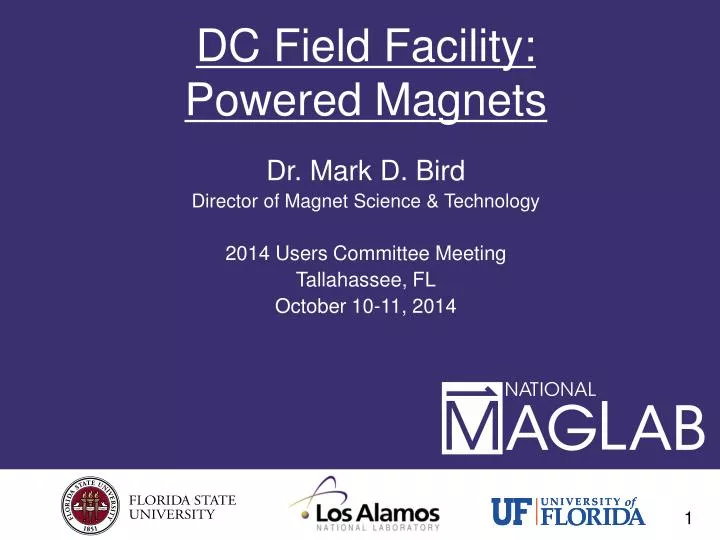
DC Field Facility:Powered Magnets Dr. Mark D. Bird Director of Magnet Science & Technology 2014 Users Committee Meeting Tallahassee, FL October 10-11, 2014
Cell 4 17 T 195mm Cell 6 25T 52mm 2ppm Cell 8 35T Cell 10 40 T 2016 Cell 12 35T Cell 14 36T SCH 2015 Cell 16 Powered (DC) Magnet CellsScott Bole, Jim O’Reilly, Chris Ray, Randy Helms, Tianlei Li Cell 2 30T 50ppm Cell 1 Cell 3 Cell 5 25 T SPLIT Cell 7 31T 50mm Cell 9 31 T 50 mm Cell 11 Cell 13 Cell 15 Hybrid 45T 3 PS Dr. Jack Toth Resistive Magnet Program Manager 8 Resistive Magnets & 1 Hybrid presently. 1 Hybrid for FSU under construction. (1 Hybrid for HZB in Testing.) Magnet bores are 32 mm unless noted otherwise.Existing, Planned Maintenance past year 13 coils stacked in the past 12 months, 7 coils installed.
25 T Hybrid For Neutron Scattering at the Helmholtz Zentrum Berlin Installation of resistive insert at HZB, May 2014. Resistive Insert Tested to Full Field June 2014. Combined-System Testing Sept. – Oct. 2014.
Hybrid Insert For HZB Conical Florida-Bitter magnet technology developed for & financed by HZB. Current-Density (A/mm2) near transition between disks of different inner diameters. Cone introduces 3-D stress-concentrations not previously encountered. Although HZB hybrid is only 25 T, its insert is the most complicated resistive magnet developed to date.
D C B A Resistive Insert for FSU/NSF 36T Series-Connected Hybrid 2 Innermost coils have reduced current-density to provide negative field-curvature to cancel that of outer coils.
Resistive Magnet Development 36 T, 24 MW Polyhelixmagnet in Grenoble, Assembled 1Q’12 Operational 1Q’14? 35 T, 19 MW, 32 mm Florida-Bitter magnet at MagLab. 2.7 m • The NHMFL had the highest field resistive magnets worldwide from 1994 – 2013. • In early 2014, French, Dutch and Chinese have surpassed the MagLab peak fields via: • Larger Magnets • More Power • MagLab developing 40 T, 28 MW, due 2016. 1.4 m 2.1 m 40 T, 28 MW Florida-Bitter magnet for MagLab, 2016. 35.6 T, 24.2 MW, 50 mmFlorida-Bitter magnet in Hefei, operational April 2014. 39 T, 28 MW Florida-Bitter magnet under construction in Hefei, operational 2014? 37.5 T, 21 MW Florida-Bitter magnet under construction in Nijmegen, operational March 2014.
High-Field Resistive Magnets Worldwide MagLab holds 6 present World Records for Resistive Magnets. MagLab is developing 5more World-Record Resistive Magnets. (Parentheses indicate magnets under development.) *sr. = steradians
45 vs 60 T Hybrids Existing 45 T 60 T Concept Cu HTS CICC LTS CICC HTS CICC LTS CICC 1.6 m 1 m 0.84 m 1.6 m The Technical Challenge of developing a 60 T hybrid today is much greater than it was to develop a 45 T hybrid in 1990. The approach today should be different than it was in 1990.
HTS cable testing 2 Existing, Operational Facilities in Tallahassee Cables can be tested w/ axial tension or transverse compression. Partnering w/ parties worldwide Solenoid 17 T, 20 cm, 20 kA Split 12 T, 15 cm, 20 kA, 250 kN
MRI Magnets 14 – 20 T The MagLab has developed conceptual designs of novel human-head MRI magnets. 14 T is relatively straight-forward scaling up of Nb3Sn CICC technology. 20 T requires development of HTS Cabled Conductors FSU Neurospin Iseult Gainesville Juelich HTS Nb3Sn NbTi only Nb3Sn Required High Temperature Superconductors NbTi
Questions? • Operating & Maintaining 9 World-Class Magnet Sites • Testing Unique 25 T Magnet for Neutrons at HZB • Fabricating Unique 36 T, 1 ppm FSU/NSF Series-Connected Hybrid • Developing 40 T, 28 MW Resistive Magnet • Developing concepts for Next-Generation Systems • 60 T Hybrid • 20 T Human Head MRI
60 T Today vs. 45 T in 1990 The Technical Challenge of developing a 60 T hybrid today is much greater than it was to develop a 45 T hybrid in 1990. The approach today should be different than it was in 1990. 45 T Outsert was a unique combination of field , current & stored enerrgy.
Hybrid Insert For HZB Installation of resistive insert at HZB, May 2014. Resistive Insert Tested to Full Field June 2014. Combined-System Testing Sept. – Oct. 2014.
Field regulation Flux Pickup Coil NMR Lock Signal Field fluctuations in the 25 T Keck. Data: J. Schiano
Field homogeneity: shims Passive (ferromagnetic) shims for Keck magnet Active (resistive) shims
Field Stabilization for FSU/NSF SCH NMR Signals vs time
Efficiency of Resistive Magnets Flux-density, B, is given by*: B = GB(α,β) (Wλ/ρa1)1/2 where GB = Geometry of coils, W = power, λ = space factor, ρ= electrical resistivity, a1= inner radius of coil. Rearrange: B(a1/W)1/2= GB(α,β) (λ/ρa1)1/2. External Properties = Internal properties = Efficiency • Other labs achieve higher fields via: • Larger Coils • Higher Power • MagLab magnets still have higher efficiency. • Most other labs use Florida-Bitter Technology. *Montgomery, Solenoid Magnet Design, Robert Krieger Publishing, 1980, p. 25.
32 T: The 1st Superconducting User Facility >23.5T Cold Bore 32 mm Uniformity 1 cm DSV 5·10-4 Ramp to 32 T 1 hour Cycles 50,000 32 T will spend most of its life ramping up and down 2.5 m Dilution refrigerator 17 T / 32 mm bore REBCO coils 15 T / 250 mm bore LTS magnet 0.9 m Coils at 4.2 K H.W. Weijers, W.D. Markiewicz, et al.
32 T Technology Development YBCO coils built prior to proposal Proposed Coils ~27x mass increase Development: • YBCO tape character-ization & quality check. • Insulation technology. • Coil winding technology. • Joint technology. • Quench analysis & protection. • Extensive Testing of Components. 320 mm High-B coils 31 T + DB MagLab Quench Protection approach is unique & more highly-developed than other approaches. No-Insulation used by some, but not suitable for 32 T. Demonstration inserts 20 T+ DB High Hoop-stress coils >700 MPa W.D. Markiewicz, H.W. Weijers, et al. Quench heater spacer
Testing of Full-Featured Prototype Coils Prototypes have all the features of real coils except fewer modules. + Additional instrumentation. 53 mm • Objectives • Confirm viability of concepts (Proceed as planned) • Active quench protection with heaters working: • Quench initiation study • Quench protection test • Measures taken to address “Helium gas bubble” successful. • Identify details requiring rework (Minimal) • Focus tasks to demonstrate next scale. • Final quench-protection design requires combined HTS-LTS analysis. Complete inner prototype coil with instrumentation and wiring. W.D. Markiewicz, H.W. Weijers, et al.
Testing 32T Prototypes in 45 T Hybrid Outsert • Realistic stress levels. • Exceed current-density. • Extensive Quench-testing. • > 20 T all SC possible. • Feb 24 – March 7, 2014. 45 T Hybrid Outsert (11.4 T) Inner & Outer Prototypes of 32 T User Magnet Assembly of Outer Prototype. Quench-heaters visible.
32 T STATUS 32 T SC magnet will constitute an 8.5 T (36%) increase in field, the largest increase since 1975! • Tested full-featured prototype Inner REBCO coil. • Initial design of Quench Protection system for 32 T. • Full-featured prototype OuterREBCO coil Feb 2014. • Construction of final REBCO coils: 2014 – 2015. • LTS Coils and Cryostat Expected from Oxford 3Q2014. • Testing of real REBCO Coils: 2Q2015. • Full-Field: 3rd Quarter 2015. • Have developed and continue to refine REBCO coil technology for 32 T high-field all-superconducting magnet. • Developed unique REBCO conductor specification, partly at 4.2 K • 12 km of final conductor ordered, ~1/2 received. • Specified and ordered LTS outer magnet + cryostat. • Relation with above vendors is collaborative. MagLab/NSF 32 T project is leading the way in HTS Coils for Routine (User) Service
32 Magnet (HTS Magnet Technology) Enables MagSci Magnets • 25 – 40 T magnets at regional facilities in US & abroad. • Neutron & x-ray scattering magnets • Design study completed for European Spallation Source. • Discussions started w/ Advanced Photon Source. • 30 T NMR • Development starting, Larbalestier’s presentation. • 20 T MRIof human brain. • Requires HTS cables. • 60 T hybrid. • Requires HTS cables.
60 T Today vs. 45 T in 1990 Is making 60 T today a similar challenge as making 45 T was in 1990? 45 T Outsert was a unique combination of field, current & stored energy. The Technical Challenge of developing a 60 T hybrid today is much greater than it was to develop a 45 T hybrid in 1990. The approach today should be different than it was in 1990.
Phase 1: HTS cable testing @ MagLab 2 Facilities 3 Cable Configurations Solenoid 17 T, 20 cm Split 12 T, 15 cm ~5- 12 mm Roebel(CI) Cable-On-Round Core (ACT) 6+ mm Twisted stack, (MIT)4 mm wide Preliminary Results To Date: 5 – 10 kA @ 15 – 17 T, ~120 A/mm2. Funding Limited.
Phase 2: Test “Small*” HTS CICC Coils to 12T • Remove all Resistive Coils, install cryostat, etc. Nb3Sn CICC HTS • Test HTS Coil @ 12 T in 510 mm bore with: • Tension • Joints • Transients • Significant Stored Energy • Coil Fabrication Technology Nb3Sn CICC HTS Coil Under High-Field Test NbTi CICC *These “Small” HTS CICC coils would be <4 MJ, < 1 ton. While this is much larger than the HTS coils needed for the 32 T magnet (0.3 MJ, 0.05 ton), they are ~1% the size of the HTS coils needed for the 60 T hybrid (~400 MJ, 25 ton).
HTS Cable Testing 2012 vs 2016 • MagLab intends to: • Expand its HTS Cable Testing program. • Develop roadmaps and seek funding for • Cable testing program: • Is relatively inexpensive. • Will also benefit other communities such as Accelerator Magnets, Fusion, Muon Accelerator, Energy Storage, etc.
50 T Hybrid Magnetusing existing Florida-Bitter and Nb3Sn CICC Technology 16 T LTS Outsert 1m bore, ~40 ton 34 T Res Insert 28 MW LTS CICC 16 T 1.2 m Res/Mag • Serve as a Test-bed for HTS Mid-Scale Coil Testing. • Serve as a User facility at 50 T. 1.2 m
40 T HTS CICC Testing 16 T LTS Outsert 1m bore, ~40 ton 34 T Res Insert 28 MW LTS CICC 16 T HTS 1.2 m Res/Mag HTS Coil Under High-Field Test • Serve as a Test-bed for HTS Mid-Scale Coil Testing. • Serve as a User facility at 50 T. 1.2 m
Testing of Intermediate-Sized HTS CICC Coil LTS CICC 16 T HTS CICC 12 + 16 T Develop LTS CICC to provide background field & stress to test Intermediate-Sized HTS coil to ~30 T. ~1 m ~0.5 m
Successful: 50 T, 14 MW User-Magnet LTS CICC 16 T HTS CICC 12 + 16 T 50 T, 14 MW 1.2 m Res/Mag 1.2 m
HTS Cable Testing Using 50T vs 45T • A 50 T Hybrid Enables: • User Facility at 50 T, 28 MW. • Development of HTS CICC Technology needed for 60T hybrid: • Testing Conductors and Coils up to ~35 T. • Testing Coils up to 30 T, ~20 MJ, ~5 tons. • Potential 50 T, 14 MW User Facility.
HTS Cable Testing 2012 vs 2016 • MagLab intends to: • Expand its HTS Cable Testing program. • Develop roadmaps and seek funding for • 20 T MRI. • 50 T Hybrid. • 60 T Hybrid. • Cable testing program: • Is relatively inexpensive. • Will also benefit other communities such as Accelerator Magnets, Fusion, Muon Accelerator, Energy Storage, etc.
Cell 4 17 T 195mm Cell 6 25T 52mm 2ppm Cell 8 35T Cell 10 40 T 2016 Cell 12 35T Cell 14 36T SCH 2015 Cell 16 DC (Powered)Magnet CellsScott Bole, Jim O’Reilly, Chris Ray, Randy Helms Cell 2 30T 50ppm Cell 1 Cell 3 Cell 5 25 T SPLIT Cell 7 31T 50mm Cell 9 31 T 50 mm Cell 11 Cell 13 Cell 15 Hybrid 45T 3 PS Dr. Jack Toth Resistive Magnet Program Manager 8 Resistive Magnets & 1 Hybrid presently. 1 Hybrid for FSU under construction. (1 Hybrid for HZB under construction.) Dr. Tianlei Li Res/Mag FEA Magnet bores are 32 mm unless noted otherwise.New,Existing, Planned Maintenance past year 10 coils stacked in the past 12 months, 10 coils installed. Magnet Unmatched worldwide Magnet Recently Surpassed Elsewhere.
Magnet Technology Dr. Mark D. Bird Director of Magnet Science and Technology NSF Site Visit of the NHMFL Tallahassee, FL February 17-19, 2014
45 vs 60 T Hybrids Existing 45 T 60 T Concept Cu LTS CICC HTS CICC HTS CICC LTS CICC 1.6 m 1 m 0.84 m 1.6 m M.D. Bird & H. Bai