Download
1 / 82
840 likes | 860 Views
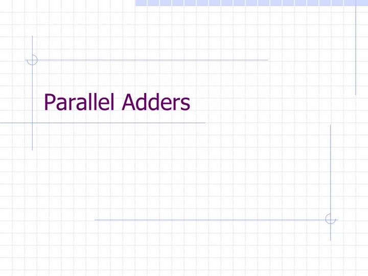
Parallel Adders. Introduction. Binary addition is a fundamental operation in most digital circuits There are a variety of adders, each has certain performance. Each type of adder is selected depending on where the adder is to be used. Adders. Basic Adder Unit Ripple Carry Adder

E N D
Introduction • Binary addition is a fundamental operation in most digital circuits • There are a variety of adders, each has certain performance. • Each type of adder is selected depending on where the adder is to be used.
Adders • Basic Adder Unit • Ripple Carry Adder • Carry Skip Adders • Carry Look Ahead Adder • Carry Select Adder • Pipelined Adder • Manchester carry chain adder • Multi-operand Adders • Pipelined and Carry save adders
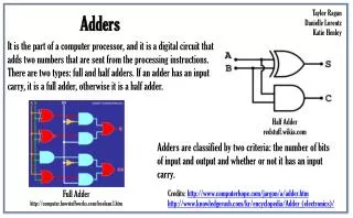
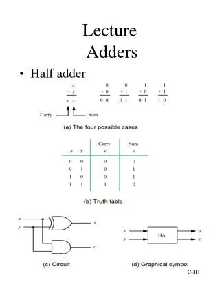
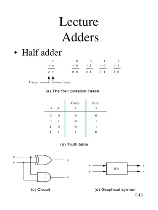
Basic Adder Unit • A combinational circuit that adds two bits is called a half adder • A full adder is one that adds three bits, the third produced from a previous addition operation P G
2. A brief introduction to Ripple Carry Adder • Reuse carry term to implement full adder Figure 2.21bit full adder CMOS complementary implementation
Ripple Carry Adder • The ripple carry adder is constructed by cascading full adder blocks in series • The carryout of one stage is fed directly to the carry-in of the next stage • For an n-bit parallel adder, it requires n full adders
Ripple Carry Drawbacks • Not very efficient when large bit numbers are used • Delay increases linearly with the bit length
Delay Critical path in a 4-bit ripple-carry adder Note: delay from carry-in to carry-out is more important than from A to carry-out or from carry-in to SUM, because the carry-propagation chain will determine the latency of the whole circuit for a Ripple-Carry adder.
Delay The latency of a 4-bit ripple carry adder can be derived by considering the above worst-case signal propagation path. We can thus write the following expression: TRCA-4bit = TFA(A0,B0→Co)+T FA (C in→C1)+ TFA (Cin→C2)+TFA (Cin→S3) And, it is easy to extend to k-bit RCA: TRCA-4bit = TFA(A0,B0→Co)+(K-2)* TFA (Cin→Ci)+TFA (Cin→Sk-1)
Design requirements Schematic diagram of a 4-bit adder No reference to implementation method Performance is important
Comparison of CMOS and TG Logic • Simulation result 4-bit RCA performance comparison of CMOS and TG logic (min size)
Comparison of CMOS and TG Logic • Simulation result 4-bit RCA performance comparison of CMOS and TG logic (Wp/Wn=2/1)
Carry Look-Ahead Adder • Calculates the carry signals in advance, based on the input signals Boolean Equations Pi = Ai Bi Carry propagate Gi = AiBi Carry generate Si = Pi Ci Sum Ci+1= Gi + PiCCarry out • Signals P and G only depend on the input bits
Carry Look-Ahead Adder • Applying these equations for a 4-bit adder: C1 = G0 + P0C0 C2 = G1 + P1C1 = G1 + P1(G0 + P0C0) = G1 + P1G0 + P1P0C0 C3 = G2 + P2C2 = G2 + P2G1 + P2P1G0 + P2P1P0C0 C4 = G3 + P3C3 = G3 + P3G2 + P3P2G1 + P3P2P1G0 + P3P2P1P0C0
Ai Gi Bi Pi Si Ci Carry Look-Ahead Structure Pi Propagate/Generate Generator Sum generator Look-Ahead Carry generator
Example Design of a large Carry Look-ahead Adder A53-----------------------------A0 B53-----------------------------B0 Carry Propagate/Generate unit P53-----------------------------P0 G53-----------------------------G0 P53-P48 G53-G48 P47-P40 G47-G40 P39-P32 G39-G32 P31-P24 G31-G24 P23-P16 G23-G16 P15-P8 G15-G8 P7-P0 G7-G0 6-Bit BCLA 8-Bit BCLA 8-Bit BCLA 8-Bit BCLA 8-Bit BCLA 8-Bit BCLA 8-Bit BCLA C53-C48 C47-C40 C39-C32 C31-C24 C23-C16 C15-C8 C7-C0 P4*G4* P5*G5* P3*-G3* P1*-G1* P6*G6* P2*-G2* P0*-G0* 7-Bit BCLA C39 C31 C23 C15 C7 C47 P53-----------------------------P0 C53-----------------------------C0 C53 54-Bit Summation Unit
Carry Skip Adders • Are composed of ripple carry adder blocks of fixed size* and a carry skip chain • The size of the blocks are chosen so as to minimize the longest life of a carry
Carry Skip Mechanics • Boolean Equations • Carry Propagate: Pi = Ai Bi • Sum: Si = Pi Ci • Carry Out: Ci+1= Ai Bi + Pi Ci • Worthwhile to note: • If Ai = Bi then Pi = 0, making the carry out, Ci+1, depend only on Ai and Bi Ci+1= Ai Bi • Ci+1= 0 if Ai = Bi= 0 • Ci+1= 1 if Ai = Bi= 1 • Alternatively if Ai Bithen Pi = 1 Ci+1= Ci
Carry Skip (example) Two Random Bit Strings: A 10100 01011 10100 01011 B 01101 10100 01010 01100 block 3 block 2 block 1 block 0 • compare the two binary strings inside each block • If all the bits inside are unequal, block 2, then the carry in from block 1 is propagated to block 3 • Carry-ins from block 2 receive the carry in from block 1 • If there exists a pair of bits that is equal carry skip mechanism fails
Manchester Carry Adder Boolean Equations: 1) Gi = Ai Bi --carry generate of ith stage 2) Pi = Ai Bi --carry propagate of ith stage 3) Si = Pi Ci --sum of ith stage 4) Ci+1 = Gi + PiCi --carry out of ith stage
Carry Select Adder Example 4-bit Adder • Is composed of two four-bit ripple carry adders per section • Both sum and carry bits are calculated for the two alternatives of the input carry, “0” and “1”
Carry Select (Mechanics) • The carry out of each section determines the carry in of the next section, which then selects the appropriate ripple carry adder • The very first section has a carry in of zero • Time delay: time to compute first section + time to select sum from subsequent sections
Carry Select Adder Design The Square Root and Linear Carry Select Adder The linear carry-select adder is constructed by chaining a number of equal-length adder stages Square Rootcarry-select adder is constructed by Equalizing the delay through two carry chains and the block-multiplexer signal from previous stage
Carry Select Adder Design The Square Root and Linear Carry Select Adder The linear carry-select adder is constructed by chaining a number of equal-length adder stages Square Rootcarry-select adder is constructed by Equalizing the delay through two carry chains and the block-multiplexer signal from previous stage
B B B B B C C C C C A A A A A A A A B B B B B B B B C C C C C C C C B B B Signal propagation in serial blocks Signal Propagation in Pipelined serial Blocks
Pipelined Adder The added complexity of such a pipelined adder pays off if long sequences of numbers are being added.
Pipelined Adder • Pipelining a design will increase its throughput • The trade-off is the use of registers • If pipelining is to be useful these three points has to be present: -It repeatedly executes a basic function. -The basic function must be divisible into independent stages having minimal overlap with each other. -The stages must be of similar complexity
16 Parallel Prefix Adder[13,15,2] The parallel prefix adder is a kind of carry look-ahead adders that accelerates a n-bit addition by means of a parallel prefix carry tree. Input bit propagate, generate, and not kill cells Output sum cells The prefix carry tree A block diagram of a prefix adder 16-bit Ladner-Fiacher parallel prefix tree black cell grey cell
17 Flagged Prefix Adder[13,15] Block diagram of a flagged prefix adder The parallel prefix adder may be modified slightly to support late increment operations. If the output grey cells are replaced by black cells so that both and signals are returned, a sum may be incremented readily.
Reference List [1] Reduced latency IEEE floating-point standard adder architectures.Beaumont-Smith, A.; Burgess, N.; Lefrere, S.; Lim, C.C.; Computer Arithmetic, 1999. Proceedings. 14th IEEE Symposium on , 14-16 April 1999 [2]M.D. Ercegovac and T. Lang, “Digital Arithmetic.” San Francisco: Morgan Daufmann, 2004. [3] Using the reverse-carry approach for double datapath floating-point addition.J.D. Bruguera and T. Lang. In Proceedings of the 15th IEEE Symposium on Computer Arithmetic, pages 203-10. [4] A low power approach to floating point adder design.Pillai, R.V.K.; Al-Khalili, D.; Al-Khalili, A.J.; Computer Design: VLSI in Computers and Processors, 1997. ICCD '97. Proceedings. 1997 IEEE International Conference on, 12-15 Oct. 1997 Pages:178 – 185 [5] An IEEE compliant floating-point adder that conforms with the pipeline packet-forwarding paradigm.Nielsen, A.M.; Matula, D.W.; Lyu, C.N.; Even, G.; Computers, IEEE Transactions on, Volume: 49 , Issue: 1, Jan. 2000 Pages:33 - 47 [6] Design and implementation of the snap floating-point adder.N. Quach and M. Flynn. Technical Report CSL-TR-91-501, Stanford University, Dec. 1991. [7] On the design of fast IEEE floating-point adders.Seidel, P.-M.; Even, G. Computer Arithmetic, 2001. Proceedings. 15th IEEE Symposium on , 11-13 June 2001 Pages:184 – 194 [8] Low cost floating point arithmetic unit design. Seungchul Kim; Yongjoo Lee; Wookyeong Jeong; Yongsurk Lee; ASIC, 2002. Proceedings. 2002 IEEE Asia-Pacific Conference on, 6-8 Aug. 2002 Pages:217 - 220 [9] Rounding in Floating-Point Addition using a Compound Adder.J.D. Bruguera and T. Lang. Technical Report. University of Santiago de Compostela. (2000) [10] Floating point adder/subtractor performing ieee rounding and addition/subtraction in parallel. W.-C. Park, S.-W. Lee, O.-Y. Kown, T.-D. Han, and S.-D. Kim. IEICE Transactions on Information and Systems, E79-D(4):297–305, Apr. 1996. [11] Efficient simultaneous rounding method removing sticky-bit from critical path for floating point addition.Woo-Chan Park; Tack-Don Han; Shin-Dug Kim; ASICs, 2000. AP-ASIC 2000. Proceedings of the Second IEEE Asia Pacific Conference on , 28-30 Aug. 2000 Pages:223 – 226 [12] Efficient implementation of rounding units Burgess.N.; Knowles, S.; Signals, Systems, and Computers, 1999. Conference Record of the Thirty-Third Asilomar Conference on, Volume: 2, 24-27 Oct. 1999 Pages: 1489 - 1493 vol.2 [13] The Flagged Prefix Adder and its Applications in Integer Arithmetic.Neil Burgess. Journal of VLSI Signal Processing 31, 263–271, 2002 [14] A family of adders.Knowles, S.; Computer Arithmetic, 2001. Proceedings. 15th IEEE Symposium on , 11-13 June 2001 Pages:277 – 281 [15] PAPA - packed arithmetic on a prefix adder for multimedia applications.Burgess, N.; Application-Specific Systems, Architectures and Processors, 2002. Proceedings. The IEEE International Conference on, 17-19 July 2002 Pages:197 – 207 [16] Nonheuristic optimization and synthesis of parallelprefix adders.R. Zimmermann, in Proc. Int.Workshop on Logic and Architecture Synthesis, Grenoble, France, Dec. 1996, pp. 123–132. [17] Leading-One Prediction with Concurrent Position Correction.J.D. Bruguera and T. Lang. IEEE Transactions on Computers. Vol. 48. No. 10. pp. 1083-1097. (1999) [18] Leading-zero anticipatory logic for high-speed floating point addition.Suzuki, H.; Morinaka, H.; Makino, H.; Nakase, Y.; Mashiko, K.; Sumi, T.; Solid-State Circuits, IEEE Journal of , Volume: 31 , Issue: 8 , Aug. 1996 Pages:1157 – 1164 [19] An algorithmic and novel design of a leading zero detector circuit: comparison with logic synthesis.Oklobdzija, V.G.; Very Large Scale Integration (VLSI) Systems, IEEE Transactions on, Volume: 2 , Issue: 1 , March 1994 Pages:124 – 128 [20] Design and Comparison of Standard Adder Schemes.Haru Yamamoto, Shane Erickson, CS252A, Winter 2004, UCLA
Adder Number of CLBs Delay (ns) Area Power Consumption (W) Ripple-Carry 16 212.79 40.00 1.7318 Carry Look-Ahead 34 143.69 51.00 1.9668 Carry-Select 44 102.74 108.00 3.3595 Comparisons Which one should we choose?
For this comparison Synopsys tools were used to perform logic synthesis. • The implemented VHDL codes for all the 64-bit adders are translated into net list files. • The virtex2 series library, XC2V250-4_avg, is used in those 64-bit adders synthesis and targeting • After synthesizing, the related power consumption, area, and propagation delay are reported. By, Chen,Kungching—M. Eng. Project_ 2005
15 Compound Adder Design[2,13-16,20] The Prefix Adder Scheme is chosen. Advantages: Simple and regular structure Well-performance A wide range of area-delay trade-offs Moreover, the Flagged Prefix Adder is particular useful in compound adder implementation because, unlike other adder schemes which need a pair of adders to obtain sum and sum+1 simultaneously, it only use one adder.
synthesis and targeting • Synopsys tools are used to perform logic synthesis. • the implemented VHDL codes for all the 64-bit adders are translated into net list files. • The virtex2 series library, XC2V250-4_avg, is used in those 64-bit adders synthesis and targeting because the area and the propagation delay is suitable for these adders. • After synthesizing, the related power consumption, area, and propagation delay are reported. • From the synthesis, the related FPGA layout schematic is reported.
64-bit adders conclusion • Adders can be implemented in different methods according to the different requirements. • Each kind of adder has different properties in area, propagation delay, and power consumption. • There is no absolute advantages or disadvantages for an adder, and usually, one advantage compensates with another disadvantage. • A ripple carry adder is easy to implemented, and for short bit length, the performances are good. • For long bit length, a carry look-ahead adder is not practical, but a hierarchical structure one can improve much.
A carry select adder has good performance in propagation delay especially the nonlinear one; however, it compensates with large area. • In these 64-bit adders, the Manchester carry adder has the best performance when considered all of the propagation delay, area, and power consumption. • The parallel prefix adder has good performance in propagation delay, but the area becomes large. • The 64-bit Kogge-Stone prefix adder has the shortest propagation delay, but it has the largest area and power consumption as well.