Download

1 / 30
300 likes | 454 Views
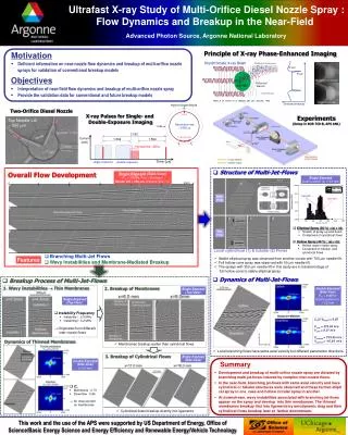
Soft X-ray Microscopy at the APS. Ian McNulty. Argonne National Laboratory. Wednesday, 9 October 2002. Many thanks to. Joe Arko Advanced Photon Source Ralu Divan Kurt Goetze Tim Mooney David Paterson Stefan Vogt Petr Ilinski Shenglan Xu Sean Frigo Northern Arizona University

E N D
Soft X-ray Microscopy at the APS Ian McNulty Argonne National Laboratory Wednesday, 9 October2002 Many thanks to ... Joe Arko Advanced Photon Source Ralu Divan Kurt Goetze Tim Mooney David Paterson Stefan Vogt Petr Ilinski Shenglan Xu Sean Frigo Northern Arizona University Cornelia Retsch Saint-Gobain Sekurit Deutschland Nathan Krapf University of Chicago Steve Wang Xradia Corporation Wenbing Yun Xradia Corporation Erik Anderson CXRO, Lawrence Berkeley National Laboratory Franco Cerrina CXRL, University of Wisconsin at Madison
Summary Motivation APS efforts Scanning microscopy Flash methods Future
1-4 keV x-rays: applications • Materials science • Nondestructive in situ imaging of buried structures • Visible/electron-opaque samples, less charging than with electrons • Contrast at K,L,M-edges in industrially important materials (AI, Si, Ti, Cu, Ga, Ge, As, Sm, Eu, Gd, W, Au, . . .) • Study electromigration and fabrication defects in chip interconnects • Biology • Better resolution than optical, less damage than electron microscopy • Specimens can be initially living, wet, unstained, and in air • Natural Na, Mg, P, S, Ca contrast in this energy range • Environmental science • Study S in soils, fossil fuels, catalyst sulfidation, lubricants • Chemical as well as elemental contrast
Magnetic materials 4-ID-C (J. Freeland) XANES PEEM MCD, MLD PEEM, scanning (future) Materials, biology 2-ID-B (D. Paterson) Transmissionscanning, holography, full-field Fluorescence scanning Tomography scanning Microdiffraction scanning Soft x-ray microscopy at APS
PEEM optics 1 mm Co Chemical and magnetic microscopy at 4-ID-C PEEM images provide direct map of chemical and magnetic structure Chemical map (Co bright) Magnetic map (M bright) Beam direction 1 mm x 1 mm x 15 nm Co nanodots on Al substrate (as dep., no field history) J. Freeland, D. Keavney, R. Winarski (APS) J. Shi, W.C. Uhlig (Univ. Utah)
2-ID-B intermediate-energy beamline Monochromaticity ~500 typ., > 3000 peak Coherent area 50 m 50 m Coherent flux2 105 ph/m2 /s/0.1% BW Focused flux4 107 ph/s/0.1% BW 50 nm spot 2 108 ph/s/0.1% BW 150 nm spot
2-ID-B SXM specifications Zone Plates Material Radius Central stop radius Zone thickness Finest zone width Transverse resolution Focal length (1.83 keV) Depth of field ( " " ) Meas. Efficiency ( " " ) Au Au Ni Ni 38.5 40 45 49 - - - 20 420 650 110 130 100 50 45 40 122 61 55 49 11.4 5.9 6.0 5.8 72 18 15 12 20 12 2.5 3.0 m µm nmnmnm mm m% Coarse Fine Sample Stage (XYZ) Linear range Linear resolution Linear velocity Angular range Angular resolution Max scan speed 25 500 2 360 0.001 0.1 0.1 0.8 20 360 0.14 0.1 mm nm mm/s degrees degrees ms/pixel
Elemental contrast in Al/W/Si chips STXM images of two-level Al/W/Si test structure at 1563 eV. SiO2 substrate was thinned to ~5 µm. Sample courtesy of DEC. STXM image at 1553 eV. Al interconnects become transparent below Al 1s edge (1559 eV), whereas W vias joining interconnects still appear dense. Steve Grantham Nat'l Inst. of Standards and Technology Zachary Levine Andy Kalukin SAIC Markus Kuhn Intel Corporation
Scanning nanotomography of AI/W/Si chips 5 µm 1 µm 500 nm 3D Bayesian reconstruction of two-level structure at 1750 eV Normal-incidence scan of electromigration void 3D reconstruction of ragged end of void Z. Levine, et al., Appl. Phys. Lett.74, 150 (1999) Z. Levine, et al., J. Appl. Phys.87, 4483 (2000)
Nanoscale metrology in Cu/W/polyimide chips (a) Schematic side view of a two-level Cu/W test structure. (b) STXM image at normal incidence. (c) Elevated surface plot. Sample courtesy of IBM. Comparison of various line scans through structure X. Su, et al., Appl. Phys. Lett. 77, 3465 (2000)
1-4 keV x-rays: biological applications • Natural contrast for nuclear and mitochondrial DNA at K-edge of P (2149 eV) • Probe cell ion transport and membrane permeability at K-edges of Na (1.09), Mg (1.28), K(3.82), Ca (4.04 keV) • Co-locate lighter elements with trace metals mapped by hard x-ray microscopy, at higher resolution • Study chemical speciation of important inorganic elements (Mg, Al, Si, Ca), e.g. in marine organisms
Phosphorus XANES P Ka fluorescence from NaPO4 P 1s absorption spectra
Simultaneous transmission, fluorescence detection Gd 3d5/2, 3d3/2 Si 1s
TiO2-DNA nanocomposites in mammalian cells • Cell is transfected with TiO2-DNA nanocomposites • DNA targets specific chromosomal region • TiO2 photocleaves DNA strands upon illumination • Potential use in gene therapy Map Ti distribution using x-ray induced K fluorescence, to quantify success rate of TiO2-DNA transfection and visualize target Affinity of transfected DNA to ribosomal DNA causes nanocomposites to localize to the nucleolus g/cm2 g/cm2 Ti 2.2 Zn 5.8 5 m 0.0 0.0 G. Woloschak, I. Moric, T. Paunesku, N. Stojicevic (Radiation Biology Dept., Northwestern Univ.)
Phosphorous absorption imaging Mouse PC-12 cell (fixed, dried) Cell nuclei, separated by centrifugation (fixed, dried) 10 µm 5 µm 5 µm Energy 2170 eV Step size 50 nm Dwell 10 ms Scan time 20 min
Energy-resolved fluorescence mapping Whole mouse PC-12 cell (fixed, dried) Detergent wash, ethidium bromide stain 5 µm Transmitted Na Ka Br La 2 µm
Nuclear contrast with P fluorescence P Ka Si Ka 5 µm Energy 2200 eV Step size 150 nm Dwell 1 s/pixel Scan time 4 h
Flash imaging methods • Holography Use x-ray optics to form reference wave and object illumination • Full-field imaging Use x-ray optics to magnify sample image • Diffraction with phase retrieval X-ray optics useful but not required
Quantitative phase contrast by holography Hologram of ~1 µm Al spheres on 100 nm formvar membrane Difference between two holograms at different foci Reconstructed phase B. Allman, A. Barty, P. McMahon, K. Nugent, D. Paganin, J. Tiller (Dept. of Physics, Univ. Melbourne) B. Allman, et al., JOSA A17, 1732 (2000) J. Tiller, Ph.D. Thesis, U. Melbourne (2001)
Full-field phase imaging Full-field image of ~2 µm spider silk Difference between in- focus, defocused images Reconstructed phase B. Allman, et al., JOSA A17, 1732 (2000)
Phase nanotomography of Si AFM tip 3D reconstructions of real part of refractive index of projections. (a, b) Horizontal slices through tip. (c) Vertical slice. (d-f) Volume renderings. Measured d = 5.0 ± 0.5 x 10⁻⁵ , calculated d = 5.1 x 10⁻⁵. P. McMahon, et al., Opt. Commun., in press
Future developments • Scanning microscope • New ZP on order (50 nm outermost zone, 450 nm Au) • Multiple SDDs to increase fluorescence acceptance • 2K x 2K fly scans • Extend quantitative phase imaging to ~50 nm level • Improve alignment for df/dz series • Solve twin-image problem with TIE • Determine limits on coherent flux required • 2-ID-B beamline • Multilayer gratings on order
1-4 keV region highly attractive for x-ray microscopy 2-ID-B SXM is a workhorse instrument at APS 50 nm (2D), 150 nm (3D) resolution simultaneous transmission and fluorescence Goal: reach photon limits near ~10 µs/pixel (transmission) ~0.1 s/pixel (fluorescence) Developing holography, coherent full-field imaging Obtain quantitative absolute phase Applicable to flash x-ray sources Beat radiation damage problem! Conclusions