Download
1 / 12
130 likes | 291 Views
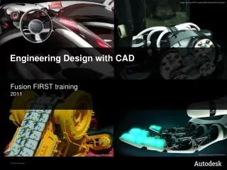
Unigraphics NX software. NX is an interactive Computer-Aided Design, Computer-Aided Manufacturing, and Computer-Aided Engineering (CAD/CAM/CAE) system. The CAD functions automate the normal engineering, design, and drafting capabilities found in today's manufacturing companies.

E N D
Unigraphics NX software NX is an interactive Computer-Aided Design, Computer-Aided Manufacturing, and Computer-Aided Engineering (CAD/CAM/CAE) system. • The CAD functions automate the normal engineering, design, and drafting capabilities found in today's manufacturing companies. • The CAM functions provide NC programming for modern machine tools using the NX design model to describe the finished part. • The CAE functions provide a number of product, assembly, and part performance simulation abilities, across a broad range of engineering disciplines. Product Design & Manufacturing, PDM I
2 - Select Model Template (plain) 3 - Select Units 4 – Specify File Name and Location Getting Started 1 - New File Product Design & Manufacturing, PDM I
Modeling – used to design parts Shape Studio – used to make your product more realistic (render, shade,..) Drafting – used to obtain 2D part drawings Assembly – used to combine parts PDM II (140) Design Simulation – used to perform FEA (finite element analysis) Motion Simulation – used to evaluate the motion of a mechanical system (mechanism) Routing Electrical – wiring, harness Routing Mechanical – Piping, Tubing NX5 Modules Select Start → Choose an Application PDM I (40) Product Design & Manufacturing, PDM I
Pull down menus View toolbar Standard toolbar Form Feature toolbar Principal planes Assembly Navigator Part Navigator Drawing area Coordinate system The Layout Product Design & Manufacturing, PDM I
Set Up Common Toolbars Right click any place in the toolbar area to bring up the Toolbar menu. Activate the desired toolbars; View, Analysis, Curve, Snap Point, Form Feature, Feature Operation, Surface, …… Product Design & Manufacturing, PDM I
Activate Different Commands in Form Feature Toolbar Select sub-menu for the desired toolbar Check the desired commands from the Add or Remove Buttons Product Design & Manufacturing, PDM I
Undo the last command Open a existing file Erase Open a New file Save a file Activate different modulus; Modeling, Drafting, shape Studio, …. Cut Copy Paste Redo the last command View toolbar Dynamic zoom in/out, hold the left mouse key down and move the mouse. Rotate the model, hold the left mouse key down and move the mouse Fit to the screen Pan (scroll) the model on the screen, hold the left mouse key down and move the mouse Open a window to zoom in Toolbars – Standard & View Standard toolbar Product Design & Manufacturing, PDM I
Select sub-menu Viewing a Solid Object 3D & 2D views of the model Product Design & Manufacturing, PDM I
Create a 2D sketch. 2.75 2.5 1.0 .75 .25 Revolved feature Extruded feature Creating Solids • Sketch a desired shape (two dimensional) and then turn it into a solid (three dimensional) by applying a desired operation. • Create a feature from the sketch by extruding, revolving, sweeping, lofting and blending. Product Design & Manufacturing, PDM I
Creating Solids from Sketches Product Design & Manufacturing, PDM I
Revolve about a center line, from 1 – 360 degrees Sweep a sketched profile along any line (guideline) Extrude along any line Sketch pad Create a Groove Create a Hole Create a Slot Create a plane to sketch on Primitive solids Creating a Solid Model – Form Feature toolbar Form Feature toolbar Product Design & Manufacturing, PDM I
Chamfer Edge Blend Create patterns Hollow solids Feature Operation Toolbar Applied features do not require a sketch. They are applied directly to the model. Fillets (edge blend) and chamfers are very common applied features. Product Design & Manufacturing, PDM I