Download

1 / 67
670 likes | 840 Views
Basic ISDN Course Layer 1 I-430. ITU-T I.430. BASIC USER-NETWORK INTERFACE – LAYER 1 SPECIFICATION. Layer 1, Physical Layer. Application. Presentation. Session. Transport. Network. Datalink. Physical. Layer 1 Characteristics.

E N D
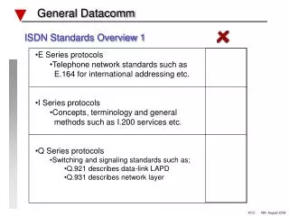
ITU-T I.430 BASIC USER-NETWORK INTERFACE –LAYER 1 SPECIFICATION
Layer 1, Physical Layer Application Presentation Session Transport Network Datalink Physical
Layer 1 Characteristics This Recommendation defines the layer 1 characteristics of the user-network interface to be applied at the S- or T‑reference points for the basic interface structure. The reference configuration for the interface is reproduced in the next slide.
NT / TE Terminology In this Recommendation, the term “NT” is used to indicate network terminating layer 1 aspects of NT1 and NT2 functional groups, and The term “TE” is used to indicate terminal terminating layer 1 aspects of TE1, TA and NT2 functional groups, unless otherwise indicated.
Service Characteristics - Layer 1 of this interface requires a balanced metallic transmission medium, for each direction of transmission, capable of supporting 192 kbit/s. - Layer 1 provides the transmission capability, by means of appropriately encoded bit streams, for the B- and D-channels and the related timing and synchronization functions. - Layer 1 provides the signaling capability and the necessary procedures to enable customer TEs and/or NTs to be deactivated when required and reactivated when required.
Service Characteristics - Layer 1 provides the signaling capability and the necessary procedures to allow TEs to gain access to the common resource of the D-channel in an orderly fashion while meeting the performance requirements of the D-channel signaling system. - Layer 1 provides the signalling capability, procedures and necessary functions at layer 1 to enable maintenance functions to be performed. - Layer 1 provides an indication to the higher layers of the status of layer 1.
Modes of Operation Both point-to-point and point-to-multipoint modes of operation, are intended to be accommodated by the layer 1 characteristics of the user-network interface. In this Recommendation, the modes of operation apply only to the layer 1 procedural characteristics of the interface and do not imply any constraints on modes of operation at higher layers.
Point to Point Operation Point-to-point operation at layer 1 implies that only one source (transmitter) and one sink (receiver) are active at any one time in each direction of transmission at an S- or T-reference point. (Such operation is independent of the number of interfaces which may be provided on a particular wiring configuration.) A point-to-point wiring configuration implies that only one source (transmitter) and one sink (receiver) are interconnected on an interchange circuit.
Point to Multipoint Operation Point-to-multipoint operation at layer 1 allows more than one TE (source and sink pair) to be simultaneously active at an S- or T-reference point. (The multipoint mode of operation may be accommodated, with point‑to-point or point-to-multipoint wiring configurations.) A point-to-multipoint wiring configuration allows more than one source to be connected to the same sink or more than one sink to be connected to the same source on an interchange circuit. Such distribution systems are characterised by the fact that they contain no active logic elements performing functions (other than possibly amplification or regeneration of the signal).
Wiring Polarity For a point-to-point wiring configuration, the two wires of the interchange circuit pair may be reversed. However, for point-to-multipoint wiring configuration, the wiring polarity integrity of the interchange circuit (TE-to-NT direction) must be maintained between TEs. In addition, the wires of the optional pairs, which may be provided for powering, may not be reversed in either configuration.
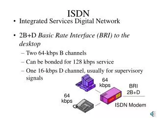
Functional Characteristics - This function provides, for each direction of transmission, two independent 64 kbit/s channels for use as B-channels - This function provides bit (signal element) timing at 192 kbit/s to enable the TE and NT to recover information from the aggregate bit stream. - This function provides 8 kHz octet timing for the NT and TE. - This function provides, for each direction of transmission, one D-channel at a bit rate of 16 kbit/s,
D-Channel Access Procedure This function is specified to enable TEs to gain access to the common resource of the D-channel in an orderly controlled fashion. The functions necessary for these procedures include an echoed D‑channel at a bit rate of 16 kbit/s in the direction NT to TE.
Frame Structure - In both directions of transmission, the bits shall be grouped into frames of 48 bits each. The frame structure shall be identical for all configurations (point-to-point and point-to-multipoint). - The nominal transmitted bit rate at the interfaces shall be 192 kbit/s in both directions of transmission. - The frame structures are different for each direction of transmission.
Frame Structure - Frames transmitted by the NT contain an echo channel (E bits) used to retransmit the D bits received from the TEs. The D-echo channel is used for D-channel access control. - The last bit of the frame (L bit) is used for balancing each complete frame. - The first bit of each frame transmitted from a TE towards the NT shall be delayed, nominally, by two bit periods with respect to the first bit of the frame received from the NT.
For both directions of transmission, pseudo-ternary coding is used with 100% pulse width as shown in the figure. Coding is performed in such a way that a binary ONE is represented by no line signal, whereas a binary ZERO is represented by a positive or negative pulse. The first binary ZERO following the frame bit-balance bit is of the same polarity as the framing bit-balance bit. Subsequent binary ZERO’s must alternate in polarity. A balance bit is a binary ZERO if the number of binary ZERO’s following the previous balance bit is odd. A balance bit is a binary ONE if the number of binary ZERO’s following the previous balance bit is even. Pseudo-Ternary Line Code
Timing The NT shall derive its timing from the network clock. A TE shall derive its timing (bit, octet, frame) from the signal received from the NT and use this derived timing to synchronise its transmitted signal.
D-channel access procedure • The following procedure allows for a number of TE’s connected in a multipoint configuration to gain access to the D‑channel in an orderly fashion. • The procedure always ensures that, even in cases where two or more TE’s attempt to access the D-channel simultaneously, one, but only one, of the TE’s will be successful in completing transmission of its information. • This procedure relies upon the use of layer 2 frames delimited by flags consisting of the binary pattern “01111110” and the use of zero bit insertion to prevent flag imitation). • The procedure also permits TE’s to operate in a point to point manner
Interframe (layer 2) time fill When a TE has no layer 2 frames to transmit, it shall send binary ONEs on the D-channel, i.e. the interframe time fill in the TE-to-NT direction shall be binary ONE’s. When an NT has no layer 2 frames to transmit, it shall send binary ONEs or HDLC flags, i.e. the interframe time fill in the NT-to-TE direction shall be either all binary ONE’s or repetitions of the octet “01111110”. When the interframe time fill is HDLC flags, the flag which defines the end of a frame may define the start of the next frame.
D-echo channel • The NT, on receipt of a D-channel bit from TE or TE’s, shall reflect the binary value in the next available D-echo channel bit position towards the TE. • It may be necessary to force the D-echo channel bits to all binary ZERO’s during certain loopbacks.
D-channel monitoring • A TE, while in the active condition, shall monitor the D-echo channel, counting the number of consecutive binary ONEs. • If a binary ZERO bit is detected, the TE shall restart counting the number of consecutive binary ONE bits. • The current value of the count is called C. NOTE – C need not be incremented after the value eleven has been reached.
Priority mechanism 1 • Layer 2 frames are transmitted in such a way that signaling information is given priority (priority class 1) over all other types of information (priority class 2). • Furthermore, to ensure that within each priority class all competing TE’s are given a fair access to the D-channel, once a TE has successfully completed the transmission of a frame, it is given a lower level of priority within the class. • The TE is given back its normal level within a priority class when all TE’s have had an opportunity to transmit information at the normal level within that priority class.
Priority mechanism 2 The priority class of a particular layer 2 frame may be a characteristic of the TE which is preset at manufacture or at installation, or it may be passed down from layer 2 as a parameter of the PH‑DATA request primitive. The priority mechanism is based on the requirement that a TE may start layer 2 frame transmission only when C is equal to, or exceeds, the value X1 for priority class 1 or is equal to, or exceeds, the value X2 for priority class 2. The value of X1 shall be eight for the normal level and nine for the lower level of priority. The value of X2 shall be ten for the normal level and eleven for the lower level of priority.
Priority mechanism 3 In a priority class the value of the normal level of priority is changed into the value of the lower level of priority (i.e. higher value) when a TE has successfully transmitted a layer 2 frame of that priority class. The value of the lower level of priority is changed back to the value of the normal level of priority when C equals the value of the lower level of priority (i.e. higher value).
Collision detection • While transmitting information in the D-channel, the TE shall monitor the received D-echo channel and compare the last transmitted bit with the next available D-echo bit. • If the transmitted bit is the same as the received echo, the TE shall continue its transmission. • If, however, the received echo is different from the transmitted bit, the TE shall cease transmission immediately and return to the D-channel monitoring state.
TE states 1 • - state F1 (Inactive): In this inactive (powered-off) state, the TE is not transmitting and cannot detect the presence of any input signals. In the case of locally powered TEs which cannot detect the appearance/disappearance of power source 1 or 2, this state is entered when local power is not present. For TEs that can detect power source 1 or power source 2, this state is entered whenever loss of power (required to support all TEI functions) is detected, or when the absence of power from power source 1 or 2, whichever power source is used for determining the connection status, is detected.
- state F2 (Sensing): This state is entered after the TE has been powered on but has not determined the type of signal (if any) that the TE is receiving. When in this state, a TE may go to a low-power consumption mode. • - state F3 (Deactivated): This is the deactivated state of the physical protocol. Neither the NT nor the TE is transmitting. When in this state, a TE may go to a low-power consumption mode. • - state F4 (Awaiting signal): When the TE is requested to initiate activation by means of a PH-ACTIVATE request primitive, it transmits a signal (INFO 1) and waits for a response from the NT. TE states 2
TE States 3 - state F5 (Identifying input): At the first receipt of any signal from the NT, the TE ceases to transmit INFO 1 and awaits identification of signal INFO 2 or INFO 4. - state F6 (Synchronized): When the TE receives an activation signal (INFO 2) from the NT, it responds with a signal (INFO 3) and waits for normal frames (INFO 4) from the NT.
TE States 4 - state F7 (Activated): This is the normal active state with the protocol activated in both directions. Both the NT and TE are transmitting normal frames. State F7 is the only state where B- and D-channel contain operational data. - state F8 (Lost framing): This is the condition when the TE has lost frame synchronization and is awaiting re-synchronization by receipt of INFO 2 or INFO 4 or deactivation by receipt of INFO 0.
NT states 1 - state G1 (Deactivated): In this deactivated state, the NT is not transmitting. When in this state, an NT may go to a low-power consumption mode. - state G2 (Pending activation): In this partially active state, the NT sends INFO 2 while waiting for INFO 3. This state will be entered on request by higher layers, by means of a PH-ACTIVATE request primitive, or on the receipt of INFO 0 or lost framing while in the active state (G3). The choice to eventually deactivate is up to higher layers within the NT.
NT states 2 - state G3 (Activated): This is the normal active state where the NT and TE are active with INFO 4 and INFO 3, respectively. A deactivation may be initiated by the NT system management, by means of an MPH‑DEACTIVATE request primitive, or the NT may be in the active state all the time, under non-fault conditions. - state G4 (Pending deactivation): When the NT wishes to deactivate, it may wait for a timer to expire before returning to the deactivated state.
Activation/deactivation procedure for TEs - All TE’s shall conform to the following: a) TE’s, when first connected, when power is applied, or upon the loss of frame alignment shall transmit INFO 0. However, a TE that is disconnected but powered is a special situation and could be transmitting INFO 1 when connected. b) TE’s shall transmit INFO 3 when frame alignment is established. However, the satisfactory transmission of operational data cannot be assured prior to the receipt of INFO 4. c) TE’s that are locally powered shall, when power is removed, initiate the transmission of INFO 0 before frame alignment is lost.
Timer Values The finite state matrix tables show timers on both the TE and the NT. The following values are defined for timers: – TE: Timer 3, not to be specified (the value depends on the subscriber loop transmission technique. The worst case value is 30 s). – NT: Timer 1, not to be specified. Timer 2, 25 to 100 ms.
TE Activation Times A TE in the deactivated state (F3) shall, upon the receipt of INFO 2 or INFO 4, establish frame synchronisation and initiate the transmission of INFO 3 within 100 ms. A TE shall recognise the receipt of INFO 4 within two frames (in the absence of errors). A TE in the “awaiting signal” state (F4) shall, upon the receipt of INFO 2 or INFO 4, cease the transmission of INFO 1 and initiate the transmission of INFO 0 within 5 ms and then respond to INFO 2 or INFO 4, within 100 ms, as above. (Note that the transition from F4 to F5 is indicated as the result of the receipt of “any signal” which is in recognition of the fact that a TE may not know that the signal being received is INFO 2 or INFO 4 until after it has recognised the presence of a signal.
NT Activation Times An NT in the deactivated state (G1) shall, upon the receipt of INFO 1, initiate the transmission of INFO 2 (synchronised to the network) within 1 s under normal conditions. Delays, “Da”, as long as 30 s are acceptable under abnormal (non-fault) conditions, e.g. as a result of a need for retrain for an associated loop transmission system. An NT in the “pending activation” state (G2) shall, upon the receipt of INFO 3, initiate the transmission of INFO 4 within 500 ms under normal conditions. Delays, “Db”, as long as 15 s are acceptable under abnormal (non-fault) conditions provided that the sum of the delays “Da” and “Db” is not greater than 30 s.
Deactivation Times A TE shall respond to the receipt of INFO 0 by initiating the transmission of INFO 0 within 25 ms. An NT shall respond to the receipt of INFO 0 or the loss of frame synchronisation by initiating the transmission of INFO 2 within 25 ms; however, the layer 1 entity does not deactivate in response to INFO 0 from a TE.
Frame Alignment procedure 1 The first bit of each frame is the framing bit, F; it is a binary ZERO. The frame alignment procedure makes use of the fact that the framing bit is represented by a pulse having the same polarity as the preceding pulse (line code violation). This allows rapid reframing. The coding rule for the auxiliary framing bit pair FA and N, in the direction NT to TE, is such that N is the binary opposite of FA (N = ). The FA and L bits in the direction TE to NT are always coded such that the binary values of FA and L are equal.