Download
1 / 10
100 likes | 260 Views
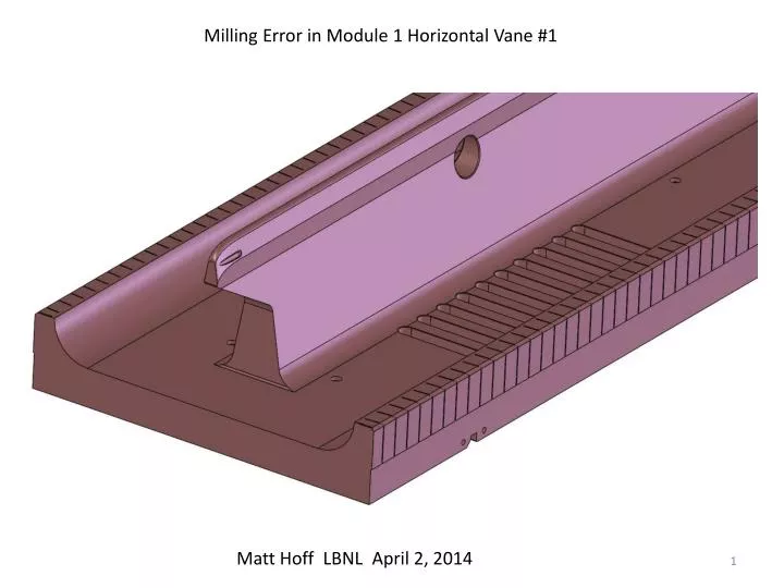
Milling Error in Module 1 Horizontal Vane #1. Matt Hoff LBNL April 2, 2014. Two views of the gouge that happened on March 24, 2014. The machinist was using a 3/8 inch ball end mill that looks something like this picture.

E N D
Milling Error in Module 1 Horizontal Vane #1 Matt Hoff LBNL April 2, 2014
The machinist was using a 3/8 inch ball end mill that looks something like this picture. The ball end mill was doing a roughing pass on the radial matcher section of the vane. After pass back and forth over the tip, creating the radial matcher section, the machinist thought the ball end mill would move away from the part and then exit towards the nose of vane. Instead the program moved the ball end mill closer to the vane and then exited towards the nose of the vane. The tool path Because this was a roughing step, there is still .030 in (.76mm) of copper left to remove after the gouge happened. The gouge in the picture is approximately 40 x 6 x 1.6 mm deep
Because there is still .030 inch of material on the radial matcher the gouge will get smaller when the machining is complete. Gouge is 1.61 mm deep - .76mm of extra material = .85mm (.034in) deep gouge in finished part. The gouge was recreated in the CAD model to visualize what it would look like when machining is complete and to create a model for analysis. The next three slide I borrowed from TianhuanLuo’s PowerPoint titled “RFQ Gouge Simulation”
B field magnitude Without gouge With gouge
E field magnitude With gouge Without gouge
Simulation results • Frequency and Q_0 differences are within numerical error of the simulation. • Local field plots show negligible effects from gouge, see next two slides.
Here is picture of the gouge after the chatter marks on the gouge surface were sanded out.
Options 1) Do nothing! Finish machining the vane and use as planned. It appears the gouge has no effect on the RFQ performance. 2) Substitute the full size test vane with the gouge vane. They are almost identical. The test vane would need some additional machining to bring it up to a production vane standard, but its mostly there. Picture shows the test vane being used to check the vane assembly fixture in January 2014 3) Use one of the spare vane blanks and start the module 1 horizontal #1 vane from scratch. Or
Don’t braze Module 1 together and postpone this repair decision until Module’s 2, 3 and 4 are fully machined and brazed together. LBNL thinks a decision on which option to use should wait until all the vanes are machined and module 2, 3 and 4 are brazed together. We should finish all machining to make sure we don’t need the spare blank vanes for a worse non-repairable machining error or a disastrous event. If we get to the point where Module’s 2, 3 and 4 are brazed together and we did not have anymore problems, we have three ways to complete Module 1. Use the gouge vane Use the full size test vane Use the blank spare vane and machine it as a Module 1 horizontal vane. Lets make this decision later, based on full completed modules and money left at that point in the project.