Download
1 / 15
160 likes | 325 Views
Abort Gap Monitoring. Randy Thurman-Keup 6 / 8 / 2004 LARP Meeting. Abort Gap Monitor. Measure the turn-by-turn synchrotron light intensity during the abort gap using a gated photomultiplier connected to a fast integrator / ADC

E N D
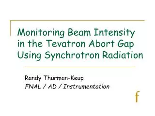
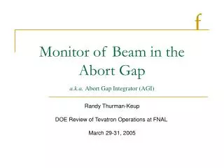
Abort Gap Monitoring Randy Thurman-Keup 6 / 8 / 2004 LARP Meeting
Abort Gap Monitor Measure the turn-by-turn synchrotron light intensity during the abort gap using a gated photomultiplier connected to a fast integrator / ADC The ADC output is accumulated and summed by front end software for 1000 turns The cycle is repeated once per second The gated PMT will share the synch light facilities via a beam splitter
Abort Gap Monitor Synch Light Box Image intensifier, CCD etc… Optional 25:1 Filter X,Y mirror Splitter Abort Gap additions Optional 100:1 Filter PMT Quartz Window Beampipe Al mirror
Abort Gap Monitor – Gated PMT The PMT has 2 dynodes connected to a pulsing circuit which holds the dynode potentials below the previous dynode to effectively block the electron flow. When the gate is applied, the dynodes are pushed up to their nominal voltages. Nominal PMT Behavior (Gated On) g Photocathode Dynodes HV below previous dynode Gated Off PMT Behavior g Photocathode Dynodes
Abort Gap Monitor – Gated PMT Gating signal
AG Monitoring – Expected Signal Want to measure DC beam at a level of 10-4 of total beam # protons in DC beam, NDC, ~109 (total beam ~1013) NDC ~ 3.6 x 10⁻³ Nbunch # abort gap protons, NAG, ~ 4.5 x 10⁻⁴ Nbunch ~ 1.3 x 10⁸ From A. Hahn Beams-doc-418: # photons / 25nm / 6 x 10¹⁰ protons ~ 3 x 10⁴ Wavelength acceptance ~ 100nm Optical losses ~ 40% efficiency (50% from beam splitter) Gating duty cycle ~ 1.5ms / ( 2.5 ms abort gap ) = 60% Nphotons ~ (3 x 10⁴) * ( 1.3 x 10⁸ / 6 x 10¹⁰ ) * 4 {100 nm acc.} * 0.4 * 0.6 Nphotons ~ 62 PMT Quantum Efficiency ~ 15% # photoelectrons ~ 9
AG Monitoring – Expected Signal PMT Signal will be fed into an integrator with a voltage out proportional to integrated charge Vout = Q * (5 x 10⁹) Gain ~ 106 Q = Npe * Gain * ( 1.6 x 10⁻¹⁹ ) ~ 1.4 pC Vout ~ ( 1.4 x 10⁻¹² ) * ( 5 x 10⁹ ) Vout ~ 7 mV ADC is 14 bit 0-1V, so roughly 100 counts
AG Monitoring – Test Setup • Setup uses pulsed LED to simulate bunch light and constant LED to simulate DC beam • Focused on trying to eliminate sensitivity of measurement to bunch light levels just prior to gating PMT, and on removing turn-on transients • Dynode 2 alone – Very Sensitive to pre-AG light • Dynode 2 and Dynode 4 – Still quite sensitive to pre-AG light • Dynode 1 and Dynode 4 – Small sensitivity to pre-AG light, but significant turn on transient (20% w/ 20ms time constant) • My theory is that the photocathode resistance is causing the turn on transient • Tried a side-on PMT to avoid the high resistivity of the transparent photocathodes • No turn on transient, similar pre-AG light sensitivity
AG Monitoring – Slow Dyn. Resp. PMT base has ~300K between dynodes; dynamic response is not good Gate start 20 usec Long transient Output of PMT into 50 ohms
AG Monitoring – Fast Dyn. Resp. PMT has capacitors between dynodes to improve dynamic response Gate start 20 usec No transient Output of PMT into 50 ohms
AG Monitoring – Dynode 2 Gating dynodes 2 and 4. Beam light transient is clearly present. Switching to dynode 1 significantly reduced the sensitivity to beam light. Gate start 2 usec Note transient Output of PMT into 50 ohms
AG Monitoring – Dynode 1 Gating dynodes 1 and 4. Even without beam light, a clear 10-20usec gating transient is present that was not present in dynode 2 version. Possibly due to photocathode resistance? In any case, can probably calibrate it away since it is reproducible. Gate start 20 usec Note transient Output of PMT into 50 ohms
AG Monitoring – Dynode 1 version Use dynodes 1 and 4 and look at sensitivity of signal to beam light. Beam light is simulated using a pulsed LED and abort gap light is simulated using an always-on LED Slide the integration window and see how long the beam light impact takes to go away
AG Monitoring • Have a viable gated PMT • Needs to be calibrated for intensity of bunches prior to gate • Backgrounds should be negligible • PMT base/gating circuit layout proceeding • Ordered a Hamamatsu gated PMT