Download
1 / 7
70 likes | 82 Views
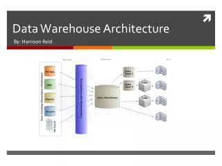
Data transport architecture over fiber and/or copper. Francesco Simeone INFN Sez. Roma. Detection Unit interface with the Optical Network. …. Tower 1. Tower 5. 2 fibers redundancy can be implemented at connector level. PJB. SJB 1. 2 fibers allow 100% redundancy. MEOC. …. SJB 18.

E N D
Data transport architecture over fiber and/or copper Francesco Simeone INFN Sez. Roma
Detection Unit interface with the Optical Network … Tower 1 Tower 5 2 fibers redundancy can be implemented at connector level PJB SJB 1 2 fibers allow 100% redundancy MEOC … SJB 18 Slow control data sent to the DUs connected to the SJB as broadcast. Data from each DU is sent to the SJB over a different fiber using a specific color.
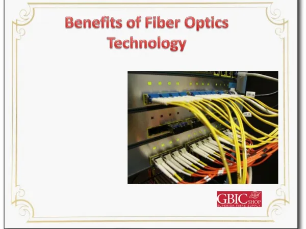
Data Transmission (1/3): Tower Backbone Backbone architecture: optical daisy chain “waterfall” scheme (1 B&W transceiver per node); data rate 1.25 Gb/s (easily expandable up to 2.5 Gb/s); accommodates up to 6 PMTs and 2 hydros per storey high optical power budget allows cheaper connectors; nodes are connected by backbone branches optical and electrical branches are separated; PRO: improved system reliability, lower cable complexity, shorter manufacture time and assembly time.
Data Transmission (1/3): Tower Backbone F19 B&W BackBone 1 Fiber 1 color per direction Backbone architecture: optical daisy chain “waterfall” scheme (1 B&W transceiver per node); data rate 1.25 Gb/s (easily expandable up to 2.5 Gb/s); accommodates up to 6 PMTs and 2 hydros per storey high optical power budget allows cheaper connectors; nodes are connected by backbone branches optical and electrical branches are separated; PRO: improved system reliability, lower cable complexity, shorter manufacture time and assembly time. F20 F17 F18 F15 F16 F3 F4 F1 F2 F0
Data Transmission (2/3): BackBone Bypass Faulty nodes can be bypassed: use a splitter per node (10:90 ratio); use an active switch per node (controlledby the independent power control system); allowed by the high optical power budget available at each hop; bypass optical loss: pass 1.1 dB and tap 10 dB; total worst case loss 11 dB (10 nodes failure case); transceivers with about 15 dB power link budget can be used (wide availability) Low power transceivers electronics: <1W per floor
Copper daisy chain architecture: • stringent limitations between cable length and max data flux; • double daisy chain: • one going up, lower speed, carries the clock: the receiver recover and regenerates the clock • one going down, carrying 1.2 Gb/s data at ~50m distance • accommodates up to 6 PMTs and 2 hydros per storey; • at the DU base an electronic board transfers the flux on optical fibre (one colour) to the optical network • copper handling safer than fibre handling, with copper cheaper connectors and components • data rate on copper limited • bypassing a faulty storey not so easy as with optical backbone Data Transmission (3/3): the copper daisy chain
V-I meter 400V/5V DC/DC converter Power Monitor & Control, Data Mux & Demux, Floor Control OptoTx OptoRx OptoTx OptoRx DWDM TX/RX Copper Odd Back Bone (OBB) Fiber Main DC 400 V Copper Even Back Bone (EBB) Fiber Spread Spectrum Drivers Tower Single Fiber TX/RX Data Transmission (3/3): Tower JB Electronics