Download
1 / 112
1.15k likes | 1.46k Views
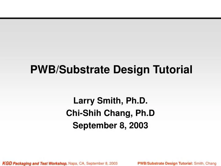
PWB/Substrate Design Tutorial. Larry Smith, Ph.D. Chi-Shih Chang, Ph.D September 8, 2003. Organization of Tutorial. Product Design Considerations (Chi-Shih Chang) Evolution to System-in-a-Package (SiP) Chip-on-Board (CoB) System-on-a-Chip (SoC) and Stacked-Die Tradeoffs SiP Implementation

E N D
PWB/Substrate Design Tutorial Larry Smith, Ph.D. Chi-Shih Chang, Ph.D September 8, 2003
Organization of Tutorial • Product Design Considerations (Chi-Shih Chang) • Evolution to System-in-a-Package (SiP) • Chip-on-Board (CoB) • System-on-a-Chip (SoC) and Stacked-Die Tradeoffs • SiP Implementation • SiP and stacked die design considerations • Substrate technologies • Electrical design • Thermomechanical design • Bare substrate testing • Assembled substrate testing • PWB Design (Larry Smith) • What’s different about PWB design using die products? • General design issues • Wirebond designs • Flip-chip designs • CAD Tools
Introductions • Larry Smith • Design Manager, K&S Substrate Division • BGA substrates for high IO flip-chip • Program Manager, MicroModule Systems • MCMs, SiPs, microBGAs • Module Manager, Dell Computer • MCM for high-volume notebook computers • Technical Director, MCC Packaging/Interconnect/HVED Program • R&D Consortium: design, fabrication, assembly, test, program management • Background • High-density thin-film interconnect • Electrical, thermal, mechanical modeling
Introductions (cont’d) • Chi-Shih Chang • SMS Micro, Inc. provides consulting services for electronics packaging and signal integrity • VP of Adv. Products, High Connection Density, Inc. • Strategic Applications Manager, K&S • Senior Fellow, Sematech • Member of the IBM Academy of Technology • Background • Semiconductor devices, IC designs, and testing • Electromagnetics and transmission lines • Electrical design and signal integrity • Packaging technologies • ITRS AP-TWG member since 1995
Organization of Tutorial • Product Design Considerations (Chi-Shih Chang) • Evolution to System-in-a-Package (SiP) • Chip-on-Board (CoB) • System-on-a-Chip (SoC) and Stacked-Die Tradeoffs • SiP Implementation • SiP and stacked die design considerations • Substrate technologies • Electrical design • Thermomechanical design • Bare substrate testing • Assembled substrate testing • PWB Design (Larry Smith) • What’s different about PWB design using die products? • Design issues • Wirebond footprint creation • Flip-chip escape routing • CAD Tools
Chip-on-Board (CoB): WB ICs • Bond fingers beyond die edges, allowing less dense PWB line width and spacing • Footprint on PWB much less than that of QFP • Reduced connection length between ICs, less series resistance, inductance & parasitic capacitance • Use low modulus die adhesive to buffer the mismatch of the coefficient of thermal expansion (CTE) of IC and that of PWB • Programmable wire bonding accommodates future die shrink without PWB redesign • Wafer-level test & burn-in, if needed
WB IC Example Source: M. Roston, et. al., “Assembly Challenges Related to Fine Pitch In-Line and Staggered Bond Pad Devices,” Proc. 53rd ECTC, May 28-30, 2003, New Orleans, pp. 1334-1343.
CoB: WLP ICs • Area array solder pads underneath die at 0.5-0.4 mm pitch, allowing relatively small number of I/Os • Footprint on PWB less than that of WB ICs • Further reduced connection length between ICs • Should reduce I/O array footprint (thus # I/Os) to a fraction of the die size to facilitate future die shrink • Wafer-level test & burn-in preferred. They may be made at die-level, if necessary
CoB: Solder Flip-Chip ICs • Area array solder pads underneath die at 0.15-0.25 mm pitch, allowing a large number of I/Os • Large number of I/O pads available for V/G connections, capable of carrying current for high power IC. They also reduce inductance and switching noise • Large number of signal I/Os for wide data bus • Very small footprint on PWB • High density PWB needed • Mismatch in CTE of IC and that of PWB presents a problem for large IC, requiring underfill encapsulation
CoB: Adhesive Flip-Chip ICs • Peripheral as well as area array connection pads underneath die at 0.1-0.2 mm pitch, allowing the maximum number of I/Os • Extremely high density PWB needed, unless number of I/O rows being limited • Minimum footprint on PWB • Adhesive serves the function of underfill encapsulant to mitigate CTE mismatch concern • Relatively low temperature at assembly • Limited current carrying capability, not suitable for high current IC
Organization of Tutorial • Product Design Considerations (Chi-Shih Chang) • Evolution to System-in-a-Package (SiP) • Chip-on-Board (CoB) • System-on-a-Chip (SoC) and Stacked-Die Tradeoffs • SiP Implementation • SiP and stacked die design considerations • Substrate technologies • Electrical design • Thermomechanical design • Bare substrate testing • Assembled substrate testing • PWB Design (Larry Smith) • What’s different about PWB design using die products? • Design issues • Wirebond footprint creation • Flip-chip escape routing • CAD Tools
SoC & Stacked-Die Tradeoffs • SoC benefits • Integrating additional functions/features, thus reducing the required number of ICs • Extremely wide bus between functions on IC • High speed connections between functions on IC • Reduced board area occupied • SoC Product Consideration (next chart)
SoC in a Competitive Marketplace • Product life & market volume may be limited • Commodity uP, uC, DSP, flash, SRAM have higher volume & lower cost • SoC targets a specific system product • Mask cost adder (approx. $ 1M per mask set) • Wafer cost • Additional process steps required to integrated analog, DRAM, flash, … etc. • Yield loss associated with additional process steps • Design time / Time-to-market • Require new IC design for each new product • Adding new product features for product upgrade • Require new IC design when adding new features
Stacked-Die Packages • Commodity ICs: uP, uC, DSP, SRAM, DRAM, Flash, Analog, RF, GaAs, ... • Ease of use • Higher level of reuse/lower cost • Faster time-to-market • Examples • Flash on SRAM (smaller die on top) • Flash on flash (same die size, a spacer needed) • Memory on baseband IC • Processor on processor • Stacked-die enabling technologies • Stacked-packages alternative
Stacked-Die Enabling Technologies • Wafer thinning • Die-to-die bonding • Low loop height wire bonding • Die attach control • Thin and dense substrate • High yield assembly process • High quality die products • Mechanical stress management • Testing
Stacked-Packages Alternative • Larger footprint and larger height than stacked-die package • Higher profile than stacked-die packages • Flexibility in supply chain • Test and burn-in at individual package level
Organization of Tutorial • Product Design Considerations (Chi-Shih Chang) • Evolution to System-in-a-Package (SiP) • Chip-on-Board (CoB) • System-on-a-Chip (SoC) and Stacked-Die Tradeoffs • SiP Implementation • SiP and stacked die design considerations • Substrate technologies • Electrical design • Thermomechanical design • Bare substrate testing • Assembled substrate testing • PWB Design (Larry Smith) • What’s different about PWB design using die products? • Design issues • Wirebond footprint creation • Flip-chip escape routing • CAD Tools
SiP Implementation • SiP applications and examples • Portable products – Cell phone, digital camera, … • Baseband processor, application processor, flash • Include passives on SiP, instead of on the motherboard (improved signal integrity) • SiP benefits
SiP Benefits • Small form factor (lower PWB cost) • Light weight for portable products • Less aggressive I/O pitch than that with COB (lower PWB cost) • Improved performance (reduced interconnect length) • Mixed IC technologies • Faster time-to-market • Ease product upgrade
Organization of Tutorial • Product Design Considerations (Chi-Shih Chang) • Evolution to System-in-a-Package (SiP) • Chip-on-Board (CoB) • System-on-a-Chip (SoC) and Stacked-Die Tradeoffs • SiP Implementation • SiP and stacked die design considerations • Substrate technologies • Electrical design • Thermomechanical design • Bare substrate testing • Assembled substrate testing • PWB Design (Larry Smith) • What’s different about PWB design using die products? • Design issues • Wirebond footprint creation • Flip-chip escape routing • CAD Tools
Substrate Technologies • Multi-layer FR-4 laminate • Add buildup layers • Photo via (photo-sensitive dielectric needed) • Laser via (general dielectric materials) • Reduce coefficient of thermal expansion (CTE) • Copper-invar-copper (CIC) to replace copper V/G reference planes • Glass ceramic • Low dielectric constant / loss materials • Reduce capacitive loading • Reduce dielectric loss for serial data communications
Organization of Tutorial • Product Design Considerations (Chi-Shih Chang) • Evolution to System-in-a-Package (SiP) • Chip-on-Board (CoB) • System-on-a-Chip (SoC) and Stacked-Die Tradeoffs • SiP Implementation • SiP and stacked die design considerations • Substrate technologies • Electrical design • Thermomechanical design • Bare substrate testing • Assembled substrate testing • PWB Design (Larry Smith) • What’s different about PWB design using die products? • Design issues • Wirebond footprint creation • Flip-chip escape routing • CAD Tools
Electrical Design • Power/ground distribution • Multiple voltages on one plane • Signal lines (To be considered a transmission line?) • Controlled impedance • Function (Line width, dielectric thickness, dielectric constant) • Signal crosstalk • Function (edge-to-edge spacing, dielectric thickness) • Noise • Magnitude of received signal depending on data pattern (noise immunity) • Propagation time depending on data patterns (timing skew) • Migrate to “differential pair”
When is 10 mm wiring a transmission line (TL)? • Time-of-flight (TOF) • 3.33 (ps/mm) x sqrt(4.0) x 10 mm = 66.7 ps • 4 TOF = 0.267 ns • A 10 mm signal wiring is to be treated as a TL when the signal rise time is less than 0.267 ns, or • f (GHz) 0.35 / 0.267 = 1.31 GHz • Important parameters: • Characteristic impedance (Zo) • Propagation time constant • Or line capacitance & inductance
Effect of a transmission line (TL) • To get a 1.0 volt signal across a 50-ohm TL, 20 mA of current is required. • When the signal line width in the PWB reduces, it may become a 60-ohm TL. At this discontinuity, the voltage becomes 1.091 volts, and the current becomes 18.2 mA. • Excessive changes in voltage and current along a signal line may increase circuit delay time, reduces noise margin, or even impact circuit functionality. • This is a burden to circuit and system designers
Zo of a Transmission Line • Zo = (377/R)/[(WEFF/H1)+(WEFF/H2)+2.62(WEFF/H1)1/4] • WEFF (W + T) / 1.5, when 0.3 T / W 0.6 Source: C.S. Chang, “Electrical Design Methodologies,” in Electronic Materials Handbook, Volume 1 Packaging, ASM International, 1989, pp. 25-44.
Zo Dependence on Design Parameters • Zo is inversely proportional to sqrt (R) • Zo increases when H1 increases • Zo decreases when W and/or T increases • Zo has weak dependence on H2, where H2 > H1 • In typical PWB, any change in W would change Zo. This discontinuity in Zo would cause signal reflection (noise)
Design Consideration for Parallel TLs • To reduce cross-talk noise, a second reference plane is very beneficial. • Reduce signal line width to maintain the same Zo. • Low cross-talk noise also reduces the effect of data patterns (in data bus and address bus) on: • Noise margin of receiver circuits • Effective signal propagation time
Two Parallel Transmission Lines One line active Adjacent line picks up noise Both lines active Common mode: both switching the same polarity Difference mode: switching on opposite polarities
Low Voltage Differential Pair • Point-to-point wiring net with far-end termination • Eliminate reflected signal (multiple bits sent before the first bit arrive at far-end) • Two signal lines for each signal port • Eliminate common mode noise (Simultaneous switching noise) • Drastically reduce signal cross-talk between adjacent pairs • (Minimize delay time dependence on data patterns in the bus) • Receiver circuit needs very small voltage swing • Reduce power consumption • Tolerate signal attenuation, less concern with skin-effect and dielectric losses (Accommodate longer line or higher frequency)
Differential Pair Transmission Lines • Two signal lines for each signal (2X wiring requirements, but reduce voltage/ground I/O#) • Immune to noise on reference planes (Tolerate a reference plane split into multiple voltages) • Low cross-talk noise from adjacent signal pairs. • Spacing within a signal pair needs tight control.
Differential Pair Transmission Lines • Low voltage swing & low power consumption • Differential receiver circuit can correctly sense an input signal even when it is attenuated to 10% or less (Single-ended receiver circuit allows attenuation at about 70%.) • Tolerate higher attenuation • Longer distance between input & output • Higher frequency • Skin effect loss proportional to square root of frequency (smooth copper surface beneficial) • Dielectric loss proportional to frequency (low loss material desirable) • Often used for broadband data communications
Organization of Tutorial • Product Design Considerations (Chi-Shih Chang) • Evolution to System-in-a-Package (SiP) • Chip-on-Board (CoB) • System-on-a-Chip (SoC) and Stacked-Die Tradeoffs • SiP Implementation • SiP and stacked die design considerations • Substrate technologies • Electrical design • Thermomechanical design • Bare substrate testing • Assembled substrate testing • PWB Design (Larry Smith) • What’s different about PWB design using die products? • Design issues • Wirebond footprint creation • Flip-chip escape routing • CAD Tools
Thermomechanical Design • Total power of all dice in a stack converted to power per unit area • Low CTE(eff) of the stacked-die causes thermomechanical stress on substrate • Not a problem for a small die • Use low modulus die adhesive, spacer and encapsulant • Use low CTE substrate