Download
1 / 49
490 likes | 719 Views
Deployment of VoIP in Data Networks. Dr. Khaled Salah salah@kfupm.edu.sa. A step-by-step Methodology. To deploy VoIP in Data Networks. Outline. Introduction and challenging questions Existing tools Drawbacks of existing tools Eight-step Methodology Case Study Analytical tool.

E N D
Deployment of VoIP in Data Networks Dr. Khaled Salah salah@kfupm.edu.sa
A step-by-step Methodology To deploy VoIP in Data Networks
Outline • Introduction and challenging questions • Existing tools • Drawbacks of existing tools • Eight-step Methodology • Case Study • Analytical tool K. Salah
Introduction • Importance of VoIP • Unification of data and voice networks • It is easier to run, manage, and maintain. • Future – NGN and Triple Play • Existing IP networks are best effort and VoIP requires QoS • Challenging questions • What are the QoS requirements for VoIP? • How will the new VoIP load impact the QoS of currently running network services and applications? • Will my existing network support VoIP and satisfy the standardized QoS requirements? • If so, how many VoIP calls can the network support before upgrading prematurely any part of the existing network hardware? K. Salah
Existing Tools • Ample of commercial tools • NetIQ • Brix Networks • Agilent • Cisco • Avaya • Siemens • Uses two common approaches for assessing the deployment of VoIP • Take network measurements and then predict the readiness based on the health of network • Inject real VoIP traffic and measure QoS K. Salah
Drawbacks of Existing Tools • Cost • Injection approach can be intrusive to operation of existing network • None offers a comprehensive approach or methodology for successful VoIP deployment. • No answers to all challenging questions, e.g. • Number of calls • Call distribution • Call flow • Future growth • Impact on existing network apps K. Salah
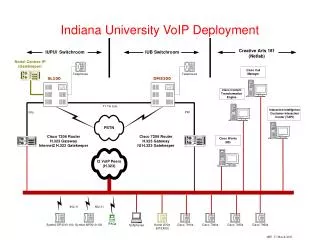
Case Study K. Salah
Methodology • Determine VoIP characteristics and requirements • Determine VoIP traffic flow and call distribution • Define performance thresholds and growth capacity • Perform network measurements • Early modifications to existing network • Theoretical Analysis • OPNET Simulation • Comparison of Simulation and Analysis • Final modifications to existing network K. Salah
VoIP Traffic Characteristics, Requirements, and Assumptions • A point-to-point conversation for all VoIP calls with no call conferencing • Hardware • Gatekeeper or CallManager • handles signaling for establishing, terminating, and authorizing connections of all VoIP calls. • H.323 or SIP • Gateway • responsible for converting VoIP calls to/from the Public Switched Telephone Network (PSTN). • VoIP Terminal • IP phones • Desktop with IP SoftPhones • As an engineering and design issue, the placement of these nodes in the network becomes crucial. K. Salah
VoIP end-to-end Components • Encoder • Packetizer • Playback Buffer • Decoder K. Salah
Common ITU-T codecs and their defaults • G.711u gives a MOS of 4.4 • Other codes use (to decrease rate): • compression • silence suppression • packet loss concealment • encapsulating voice packets in one Ethernet frame K. Salah
End-to-End Delay for a Single Voice Packet • The end-to-end delay is sometimes referred to by M2E or Mouth-to-Ear delay • G.714 imposes a maximum total one-way packet delay of 150ms end-to-end for VoIP applications • 200ms was found to be acceptable by experimentation • Sources of delay: (i) encoding, compression, and packetization delay at the sender (ii) propagation, transmission and queuing delay in the network (iii) buffering, decompression, depacketization, decoding, and playback delay at the receiver. K. Salah
VoIP Traffic Characteristics and Requirements • M2E delay for a single call • 150ms according to G.714 • Sender: 25 ms • Receiver: 45 ms • Higher than the sender. It includes jitter buffer delay which is at most 2 packets or 40 ms • Network: 80 ms K. Salah
Bandwidth for a Single Call • The required bandwidth for a single call, one direction, is 64 kbps. • G.711 codec samples 20ms of voice per packet. Therefore, 50 such packets need to be transmitted per second. • Each packet contains 160 voice samples in order to give 8000 samples per second. PCM sampling & quantization is done every 125us. • Each packet is sent in one Ethernet frame. With every packet of size 160 bytes, headers of additional protocol layers are added. These headers include RTP + UDP + IP + Ethernet with preamble of sizes 12 + 8 + 20 + 26, respectively. • Therefore, a total of 226 bytes, or 1808 bits, needs to be transmitted 50 times per second, or 90.4 kbps, in one direction. • For both directions, the required bandwidth for a single call is 100 pps or 180.8 kbps assuming a symmetric flow. K. Salah
Other Assumptions • Voice calls are symmetric and no voice conferencing • We also ignore the signaling traffic generated by the gatekeeper. • Worst-case scenario is considered • signaling traffic involving the gatekeeper is mostly generated prior to the establishment of the voice call and when the call is finished. This traffic is relatively small compared to the actual voice call traffic. • gatekeeper generates no or very limited signaling traffic throughout the duration of the VoIP call for an already established on-going call • No QoS mechanisms that can enhance the quality of packet delivery in IP networks, such as • IEEE 802.1p/Q • IETF’s RSVP • DiffServ • MPLS K. Salah
VoIP Traffic Flow and Call Distribution • Knowing the current telephone call usage or volume of the enterprise is an important step for a successful VoIP deployment. • Collecting statistics about of the present call volume and profiles is essential. • Sources • PBX database • Telephone records • Billing • Key characteristics of existing calls can include the number of calls, number of concurrent calls, time, duration, etc • We want to investigate if these characteristics can be still met when migrating to VoIP • Locations of the call endpoints, i.e., the sources and destinations, as well as their corresponding path or flow • Call distribution must include percentage of calls within and outside of a floor, building, department, or organization. • As a good capacity planning measure, it is recommended to base the VoIP call distribution on the busy hour traffic of phone calls for the busiest day of a week or a month. • The projected extra calls need to be also combined with current statistics K. Salah
Call Distribution K. Salah
Define Performance Thresholds and Growth Capacity • The maximum tolerable end-to-end delay • determined by the most sensitive application to run on the network • 150ms for VoIP • It is imperative to note that if the network has certain delay-sensitive applications, the delay for these applications should be monitored, when introducing VoIP traffic, such that they do not exceed their required maximum values. • The utilization bounds or thresholds of network resources • Factors to consider: current utilization, future plans, and foreseen growth of the network. • It is extremely important not to utilize fully the network resources. • Packet loss • Depends on network service or application • For VoIP, 0.1% to 5% packet loss is acceptable K. Salah
Future Growth • What is the projected growth in users, network services, business, etc.? • In our study we will ascertain that 25% of the available network capacity is reserved for future growth and expansion. • we will apply this evenly to all network resources of the router, switches, and switched-Ethernet links. K. Salah
Perform Network measurements • Need to characterize the existing network traffic load, utilization, and flow • Background traffic profiling • Available tools: • Open-source • MRTG, STG, SNMPUtil, and GetIF • Commercial • HP OpenView, Cisco Netflow, Lucent VitalSuite, Patrol DashBoard, Omegon NetAlly, Avaya ExamiNet, NetIQ Vivinet Assessor, etc. K. Salah
Perform Network measurements • Network measurements must be performed for network elements such as routers, switches, and links. • Numerous types of measurements and statistics can be obtained using measurement tools. • As a minimum, traffic rates in bps (bits per second) and pps (packets per second) must be measured for links directly connected to routers and switches. • To get adequate assessment, network measurements have to be taken over a long period of time, at least 24-hour period. • Sometimes it is desirable to take measurements over several days or a week. K. Salah
Worst-case network measurements K. Salah
Upfront Network Assessment and Modifications • Examine if any immediate modifications are necessary • may include adding and placing new servers or devices, upgrading PCs, and re-dimensioning heavily utilized links. • As a good upgrade rule, topology changes need to be kept to minimum and should not be made unless it is necessary and justifiable. Over-engineering the network and premature upgrades are costly and considered as poor design practices K. Salah
Changes to topology • Links are underutilized, no need for 1G links • Shared links must be replaced with full-duplex switched • shared Ethernet offers zero QoS and are not recommended for real-time and delay-sensitive applications as it introduces excessive and variable latency under heavy loads and when subjected to intense bursty traffic • Add gatekeeper and gateway • connecting the gatekeeper to Switch 1 is practical in order to keep the traffic local. • Connecting the gateway to Switch 2 balances the projected load on both switches. • It is more reliable and fault-tolerant not to connect both nodes to the same switch in order to eliminate problems that stem from a single point of failure. K. Salah
Original Topology K. Salah
New Topology with VoIP Components K. Salah
The analytical approach • Bandwidth bottleneck analysis • Delay analysis • The actual number of VoIP calls that the network can sustain and support is bounded by those two metrics. • Depending on the network under study, either the available bandwidth or delay can be the key dominant factor in determining the number of calls that can be supported. K. Salah
BW bottleneck analysis K. Salah
Network Delay Analysis • Poisson VoIP Traffic • Using Jackson Theorem • Links: M/D/1 • Router and Switches: M/M/1 K. Salah
Network Capacity Algorithm • Add background traffic • Add one call based on distribution and flow • For each node calculate the new arrival rate – not all nodes are affected. • Compute packet network delay for all flows by summing up individual delays per node • If network delay < 80 ms, go to ii, otherwise STOP. K. Salah
Analytical Tool • Generic • GUI • With drag-and-drop features • Analytical engine • BW bottleneck analysis • Compute iteratively the network delay K. Salah
Simulation • Using OPNET • Will be discussed in great detail in next presentation K. Salah
Comparison • A way to validate results of both simulation and analysis (or expert intuition). K. Salah
Pilot Deployment • Before embarking on changing any of the network equipment, it is always recommended to build a pilot deployment of VoIP in a test lab to ensure smooth upgrade and transition with minimum disruption of network services. • A pilot deployment is the place for the network engineers, support and maintenance team to get firsthand experience with VoIP systems and their behavior. • New VoIP devices and equipment are evaluated, configured, tuned, tested, managed, monitored, etc. • Get comfortable with how VoIP works, how it mixes with other traffic, how to diagnose and troubleshoot potential problems. • Simple VoIP calls can be set up and some benchmark testing can be performed. K. Salah
To Summarize • A step-by-step methodology on how VoIP can be deployed successfully • The methodology can help network researchers and designers to determine quickly and easily how well VoIP will perform on a network prior to deployment. • Prior to the purchase and deployment of VoIP equipment, it is possible to predict the number of VoIP calls that can be sustained by the network while satisfying QoS requirements of all existing and new network services and leaving enough capacity for future growth. K. Salah