Download
1 / 14
140 likes | 302 Views
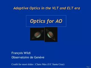
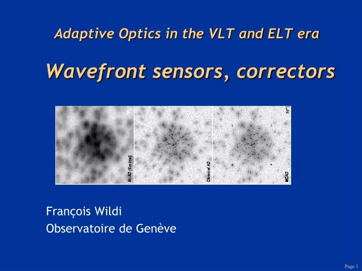
Adaptive Optics in the VLT and ELT era Wavefront sensors, correctors. François Wildi Observatoire de Genève. Issues for designer of AO systems. Performance goals: Sky coverage fraction, observing wavelength, degree of compensation needed for science program Parameters of the observatory:

E N D
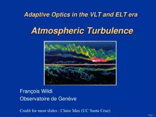
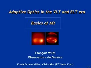
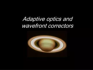
Adaptive Optics in the VLT and ELT eraWavefront sensors, correctors François Wildi Observatoire de Genève
Issues for designer of AO systems • Performance goals: • Sky coverage fraction, observing wavelength, degree of compensation needed for science program • Parameters of the observatory: • Turbulence characteristics (mean and variability), telescope and instrument optical errors, availability of laser guide stars • AO parameters chosen in the design phase: • Number of actuators, wavefront sensor type and sample rate, servo bandwidth, laser characteristics • AO parameters adjusted by user: integration time on wavefront sensor, wavelength, guide star mag. & offset
Dependence of Strehl on l and number of DM degrees of freedom • Assume bright natural guide star • No meas’t error or iso-planatism or bandwidth error Deformable mirror fitting error only
Reminder #1: Dependence of Strehl on l and number of DM degrees of freedom (fitting) Decreasing fitting error • Assume bright natural guide star • No meas’t error or iso-planatism or bandwidth error Deformable mirror fitting error only
Existing MEMS mirror (sufficient for Hybrid-MOAO) Boston Micromachines 32x32 actuator, 1.5 um MEMS device. (In Stock)
Basics of wavefront sensing Guide star Recon-structor Telescope Detector Optics Turbulence • Measure phase by measuring intensity variations • Difference between various wavefront sensor schemes is the way in which phase differences are turned into intensity differences • General box diagram: Wavefront sensor Computer Transforms aberrations into intensity variations
Types of wavefront sensors • “Direct” in pupil plane: split pupil up into subapertures in some way, then use intensity in each subaperture to deduce phase of wavefront. REAL TIME • Slope sensing: Shack-Hartmann, pyramid sensing • Curvature sensing • “Indirect” in focal plane: wavefront properties are deduced from whole-aperture intensity measurements made at or near the focal plane. Iterative methods - take a lot of time. • Image sharpening, multi-dither • Phase diversity
Shack-Hartmann wavefront sensor concept - measure subaperture tilts f Pupil plane Image plane CCD CCD
WFS implementation • Compact • Time-invariant
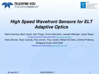
CCD rapide • CCD design complete • 64 pins • 256x256 pixels • 1200 trames/s • < 1e bruit • Refroidissment Peltier PF Vis AO WFS
PF Vis AO WFS OP 4 Gain Registers Metal Buttressed 2Φ 10 Mhz Clocks for fast image to store transfer rates. 8 L3Vision Gain Registers/Outputs. Each 15Mpix./s. OP 3 OP 2 Gain Registers Store slanted to allow room for multiple outputs. OP 1 Image Area 240x120 24□µm Image Area 240x120 24□µm OP 8 OP 6 Gain Registers Gain Registers Store Area Store Area OP 7 OP 5 Split frame transfer 8-output back-illuminated e2v L3Vision CCD for WFS.
TMT.IAO.PRE.06.030.REL02 3. NGS WFS • Radial+Linear stages with encoders offer flexile design with min. vignetting • 6 probe arms operating in “Meatlocker” just before focal plane • 2x2 lenslets • 6” FOV - 60x60 0.1” pix EEV CCD60 Flamingos2 OIWFS