Download
1 / 44
440 likes | 558 Views
The VIRGO Environmental Monitoring System. R. De Rosa University of Napoli - Federico II and INFN - Napoli. Environmental Monitoring Overview. - Slow Monitoring System Environmental Monitoring System Seismic Probes Magnetic Probes Acoustic Probes Probe Location in VIRGO

E N D
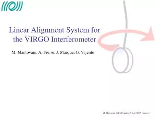
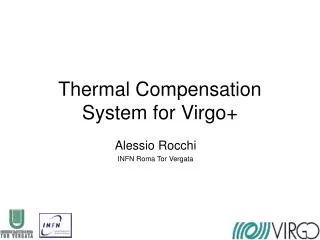
The VIRGOEnvironmental Monitoring System R. De Rosa University of Napoli - Federico II and INFN - Napoli
Environmental Monitoring Overview • - Slow Monitoring System • Environmental Monitoring System • Seismic Probes • Magnetic Probes • Acoustic Probes • Probe Location in VIRGO • Probes connected with ITF control • Future Projects (R&D)
Environmental Monitoring Overview The Environmental Monitoring system is divided in two subsystems: 1 – The Slow Environmental Monitoring subsystem, also identified as Building Control System is used to collect all the slow environmental monitoring signals. 2 – The Fast Environmental Monitoring subsystem, properly the Environmental Monitoring System, provides for the signal coming from standard environmental probes. Many other probes exists in Virgo, mainly devoted to the sensing and control of the interferometer: suspensions system, detector motion, …
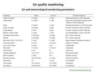
Building Control System • The Building Control System was originally designed to monitor some environmental parameters inside the buildings. • Up to now the parameters are: • Temperature; • Pressure; • Humidity; • -Weather parameters: wind speed and direction, internal and external temperature, internal and external humidity, internal pressure, rain rate • -Lightning parameter: number of strikes, strike distance, strike angle.
Building Control System Data coming from the probes are first transformed in suitable voltage by a conditioning electronic Conditioning electronic Probes
Building Control System Standard slow monitoring probes require a suitable conditioning electronics. For temperature, pressure and humidity probes it is an home made electronics, directly placed inside the acquisition boxes.
Building Control System Then they are digitised by an analog to digital converter (ADC) with 12 bits resolution and ± 10 V of input range. 16 Channels ADC 12 bit Conditioning electronic Probes
Building Control System The digital data are collected by a local board 16 Channels ADC 12 bit ETN BOARD Conditioning electronic Probes
Building Control System This system it is called an Acquisition Box 16 Channels ADC 12 bit ETN BOARD Conditioning electronic Probes
Building Control System Digital data are sent, through a physical link, to the main controller. 16 Channels ADC 12 bit ETN BOARD Conditioning electronic ETN CONTROLLER Probes
Building Control System Several Acquisition box are connected on the same link 16 Channels ADC 12 bit ETN BOARD 1 ETN BOARD ...N ETN LINK Conditioning electronic ETN CONTROLLER Probes
Building Control System The controller collects the data coming from all the remote acquisition board and sent them to the master CPU through the VME bus 16 Channels ADC 12 bit ETN BOARD 1 ETN BOARD ...N ETN LINK Conditioning electronic ETN CONTROLLER MASTER VME CPU Probes VME BUS
Building Control System Finally the master CPU sent the data to the slow frame builder through the network 16 Channels ADC 12 bit ETHERNET LINK ETN BOARD 1 ETN BOARD ...N ETN LINK Conditioning electronic ETN CONTROLLER MASTER VME CPU Probes VME BUS
Building Control System The data coming from the Weather Station and from the Lightning Detector are sent directly to the master CPU through a RS232 link. 16 Channels ADC 12 bit ETHERNET LINK ETN BOARD 1 ETN BOARD ...N Weather Station ETN LINK RS232 LINK Conditioning electronic ETN CONTROLLER MASTER VME CPU Lightning Detector Probes VME BUS
Building Control System The meteo station is composed by an integrated sensor that provides for: Temperature, Humidity, Rain Rate, Wind Speed, Wind Direction; And a console that provides for: Temperature, Humidity, Pressure; Moreover the console fully manages the integrated sensors. The data are available in digital format on a serial link
Building Control System The lightning detector includes a console. This provides for digital data that can be acquired by using a serial link.
Environmental Monitoring Fast Probes • The second subsystem is composed by the fast probes. • All these probes are connected directly to the fast frame builder through a conditioning electronic. • Actually there are four kinds of fast probes: • - Seismometers: • Episensors; • Accelerometers; • Velocimeters; • - Microphones; • - Magnetometers. ETHERNET LINK Fast Frame Builder Conditioning electronic Probes
Environmental Monitoring Accelerometers The Accelerometers uses a commercial conditioning amplifier (Nexus). This amplifiers also filters the data in the desired band. Actually the band is: 1Hz – 3 kHz The sensitivity is around 36 pC/ms-2
Environmental Monitoring Accelerometers The operating principle is based on the force exerted by the seismic mass on the piezoelectric transducer that produce an electrical charge. The charge is measured by the amplifiers and converted in a voltage M=Seismic Mass, P=Piezoelectric Element B=Base R=Clamping Ring
Environmental Monitoring Accelerometers The filtering of the output signal is performed by the conditioning amplifier. It is a simple band pass filter (double zero-pole)
Environmental Monitoring Seismometers Seismometers: There are two kind of seismometers: Guralp (velocimeter), Episensors (accelerometer). Both of them use an home made conditioning electronics to amplify the output signal and to filter it before the local read-out ADC. Actually the band is 0 – 200 Hz. Both the sensors are tri-axial.
Environmental Monitoring Episensor Operating Scheme All
Environmental Monitoring Episensor Operating Scheme • An acceleration causes the coil and capacitive sensor plates to move with respect to the fixed central plate of the capacitive transducer; • -This displacement results in a signal on the center plate of the capacitor becoming unbalanced; • The amplifier amplifies this signal; • The feedback loop compensates for this error signal by passing current through the coil to create a magnetic restoring force to "balance" the capacitor plates back to their original null position; • This signal is proportional to the acceleration needed to restore the mass position, i.e. to the external acceleration acting on the sensor.
Environmental Monitoring Episensor The frequency bandwidth is about 200 Hz; The sensitivity is selectable. The current choice is 40 V/g; Even if the sensor is capable to measure DC accelerations, its response become poor for frequency lower than 100 mHz; Under this frequency other effects become dominant (temperature change, elecrtonic noise, …)
Environmental Monitoring Episensor Since the sensor sensitivity is low respect to the ADC dynamic range, the signals are amplified by a factor 100 and filtered (200 Hz) to avoid the aliasing.
Environmental Monitoring Velocimeters • - The operating principle of these sensors is similar to the episensor one; • The main difference is that the output signal is proportional to the speed of the moving mass; • The frequency bandwidth of the sensor span from 0.033 Hz to 50 Hz; • The same conditioning electronics (100x Gain and 200 Hz anti aliasing filters) is used before the ADC;
Environmental Monitoring Monitoring an Earthquake
Environmental Monitoring Magnetometers The magnetometers are single axis probes. They are always placed in set of three, one for each direction. They have a built-in conditioning electronics that requires no other conditioning to the local read-out. The signal is also filtered in the band: 4 Hz – 8.192 kHz
Environmental Monitoring Magnetometers Each magnetometer consists of a sensor coil and a conditioning amplifier integrated in the sensor. The sensor coil: it consists of a high permeable ferrite core and several thousand copper turns The conditioning amplifier: it consists of low noise amplifiers used to reach suitable voltage levels at the sensor output The sensor coil is sensitive to the time derivative of the magnetic flux inside the coil.
Environmental Monitoring Magnetometers The operating principle of the sensor is the following
Environmental Monitoring Magnetometers The sensitivity of these probes is very high
Environmental Monitoring Magnetometers A typical behaviour of a good magnetic spectrum (at VIRGO site), compared with the noise level of the sensor.
Environmental Monitoring Magnetometers Magnetic effect of a lighting strike
Environmental Monitoring Microphones The Microphones uses a commercial conditioning amplifier (Nexus). This amplifiers also filters the data in the desired band. For the microphones the band is: 0.1Hz – 3 kHz; The sensitivity is 1 V/Pa
Environmental Monitoring Microphones The filtering of the output signal is performed by the conditioning amplifier. It is a simple band pass filter (double zero-pole)
T T T T T T T T T T T T T T T T T E E E E B B M M M M M Microphone P P P P P P Magnetometer V V Episensor A A A A A A A A A A A Velocimeter H H H H H H Accelerometer Temperature Probe Pressure Probe Humidity Probe Probes Location (Central Building)
T T T E E B M M Microphone P P Magnetometer V Episensor A A Velocimeter H H Accelerometer Temperature Probe Pressure Probe Humidity Probe Environmental Monitoring Probes Location (Mode Cleaner)
T T T T T T T E E B B M M Microphone P P P Magnetometer V Episensor A A A Velocimeter H H H Accelerometer Temperature Probe Pressure Probe Humidity Probe Environmental Monitoring Probes Location (North End)
T T T T T T E E B B M M Microphone P P P Magnetometer V Episensor A A A Velocimeter H H H Accelerometer Temperature Probe Pressure Probe Humidity Probe Environmental Monitoring Probes Location (West End)
Environmental Monitoring Further informations are available on the VIRGO web pages: Probe List and Information http://wwwcascina.virgo.infn.it/EnvMon/List/ Probe characteristics: http://wwwcascina.virgo.infn.it/EnvMon/Sensors
Environmental Monitoring ITF Sensors Many other sensors are available, but they are more connected with the sensing and control of the ITF; The most interesting are the sensors used for the control of the superattenuator They consist mainly in accelerometers and position sensor used to control the first stage of the suspended stage (Filter Zero)
Environmental Monitoring ITF Sensors These probes are very sensitive to ground vibration, induced by earthquakes or by strong wind; Since the accelerometers are used for the feed-back in the range 30 mHz – 2 Hz, their output is always close to zero; In this way the main information is carried by the positions sensors;
Environmental Monitoring Future Sensors • The actual sensors used for the suspension control need to be improved to meet the performances required for Advancd Virgo; • In particular: • More sensitive accelerometers may be required; • Tilt meters are required to increase the duty-cycle of the interferometer in bad weather condition; • In this case, in fact, a significant tilt may be induced by the building motion, and the accelerometers interpreter this effect as an acceleration, resulting in a wrong correction;
Environmental Monitoring Future Sensors Also a prototype of a monolythic accelerometers is currently developing in Virgo (INFN Napoli – Salerno University)