Download
1 / 1
10 likes | 151 Views
12 – Lead ECG Trainer. All subjects view introductory placement video. All subjects pre-test on mannequin without use of LED’s. Record results. Group 1:. Group 2:. Train individually with mannequin for 15 minutes. Train one-on-one with instructor for 15 minutes.

E N D
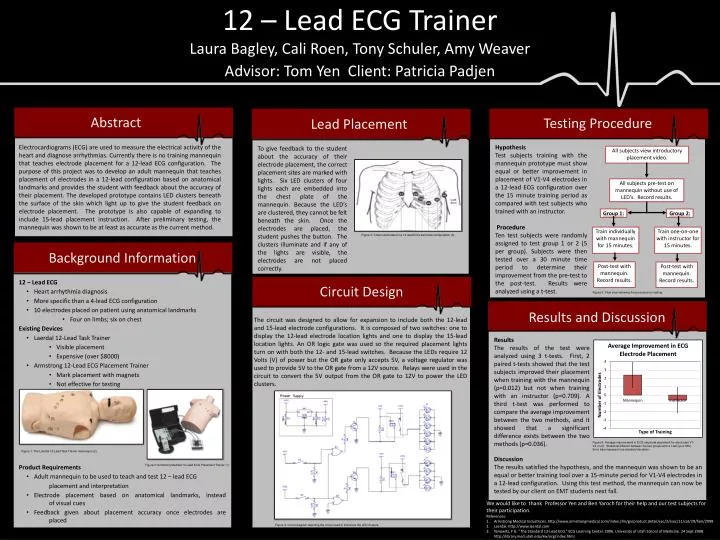
12 – Lead ECG Trainer All subjects view introductory placement video. All subjects pre-test on mannequin without use of LED’s. Record results. Group 1: Group 2: Train individually with mannequin for 15 minutes. Train one-on-one with instructor for 15 minutes. Post-test with mannequin. Record results. Post-test with mannequin. Record results. Laura Bagley, Cali Roen, Tony Schuler, Amy Weaver Advisor: Tom Yen Client: Patricia Padjen Abstract Testing Procedure Lead Placement Electrocardiograms (ECG) are used to measure the electrical activity of the heart and diagnose arrhythmias. Currently there is no training mannequin that teaches electrode placement for a 12-lead ECG configuration. The purpose of this project was to develop an adult mannequin that teaches placement of electrodes in a 12-lead configuration based on anatomical landmarks and provides the student with feedback about the accuracy of their placement. The developed prototype contains LED clusters beneath the surface of the skin which light up to give the student feedback on electrode placement. The prototype is also capable of expanding to include 15-lead placement instruction. After preliminary testing, the mannequin was shown to be at least as accurate as the current method. Hypothesis Test subjects training with the mannequin prototype must show equal or better improvement in placement of V1-V4 electrodes in a 12-lead ECG configuration over the 15 minute training period as compared with test subjects who trained with an instructor. Procedure Ten test subjects were randomly assigned to test group 1 or 2 (5 per group). Subjects were then tested over a 30 minute time period to determine their improvement from the pre-test to the post-test. Results were analyzed using a t-test. To give feedback to the student about the accuracy of their electrode placement, the correct placement sites are marked with lights. Six LED clusters of four lights each are embedded into the chest plate of the mannequin. Because the LED’s are clustered, they cannot be felt beneath the skin. Once the electrodes are placed, the student pushes the button. The clusters illuminate and if any of the lights are visible, the electrodes are not placed correctly. Figure 3: Chest electrodes for a 12-lead ECG electrode configuration (3).. Background Information • 12 – Lead ECG • Heart arrhythmia diagnosis • More specific than a 4-lead ECG configuration • 10 electrodes placed on patient using anatomical landmarks • Four on limbs; six on chest • Existing Devices • Laerdal 12-Lead Task Trainer • Visible placement • Expensive (over $8000) • Armstrong 12-Lead ECG Placement Trainer • Mark placement with magnets • Not effective for testing • Product Requirements • Adult mannequin to be used to teach and test 12 – lead ECG placement and interpretation • Electrode placement based on anatomical landmarks, instead of visual cues • Feedback given about placement accuracy once electrodes are placed Circuit Design Figure 5: Flow chart showing the procedure for testing. Results and Discussion The circuit was designed to allow for expansion to include both the 12-lead and 15-lead electrode configurations. It is composed of two switches: one to display the 12-lead electrode location lights and one to display the 15-lead location lights. An OR logic gate was used so the required placement lights turn on with both the 12- and 15-lead switches. Because the LEDs require 12 Volts (V) of power but the OR gate only accepts 5V, a voltage regulator was used to provide 5V to the OR gate from a 12V source. Relays were used in the circuit to convert the 5V output from the OR gate to 12V to power the LED clusters. Results The results of the test were analyzed using 3 t-tests. First, 2 paired t-tests showed that the test subjects improved their placement when training with the mannequin (p=0.012) but not when training with an instructor (p=0.709). A third t-test was performed to compare the average improvement between the two methods, and it showed that a significant difference exists between the two methods (p=0.036). Figure 6: Average improvement in ECG electrode placement for electrodes V1-V4 (n=5). Statistical different between the two groups with a t-test (p=0.036). Error bars represent one standard deviation. Figure 1: The Laerdal 12-Lead Task Trainer mannequin (2). Discussion The results satisfied the hypothesis, and the mannequin was shown to be an equal or better training tool over a 15-minute period for V1-V4 electrodes in a 12-lead configuration. Using this test method, the mannequin can now be tested by our client on EMT students next fall. Figure 2: Armstrong Medical 12-Lead ECG Placement Trainer (1). • We would like to thank Professor Yen and Ben Yaroch for their help and our test subjects for their participation. • References: • Armstrong Medical Industrices. http://www.armstrongmedical.com/index.cfm/go/product.detail/sec/2/ssec/11/cat/29/fam/2098 • Laerdal. http://www.laerdal.com • Yanowitz, F G. “The Standard 12-Lead ECG.” ECG Learning Center. 2006. University of Utah School of Medicine. 24 Sept 2008. http://library.med.utah.edu/kw/ecg/index.html. Figure 4: Circuit diagram depicting the circuit used to illuminate the LED clusters.