Download
1 / 11
130 likes | 382 Views
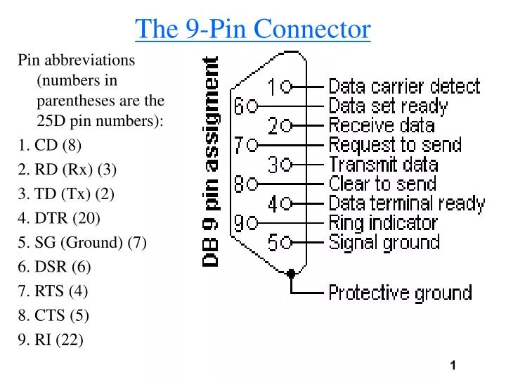
The 9-Pin Connector. Pin abbreviations (numbers in parentheses are the 25D pin numbers): 1. CD (8) 2. RD (Rx) (3) 3. TD (Tx) (2) 4. DTR (20) 5. SG (Ground) (7) 6. DSR (6) 7. RTS (4) 8. CTS (5) 9. RI (22). Connecting Via Modems.

E N D
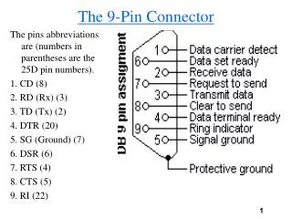
The 9-Pin Connector Pin abbreviations (numbers in parentheses are the 25D pin numbers): 1. CD (8) 2. RD (Rx) (3) 3. TD (Tx) (2) 4. DTR (20) 5. SG (Ground) (7) 6. DSR (6) 7. RTS (4) 8. CTS (5) 9. RI (22)
Connecting Via Modems • The serial interface is between the computer and the modem. • Public Switched Telephone Network
The Control Lines • DTR (Data Terminal Ready) - Indicates to the modem that the UART is ready to communicate. • DSR (Data Set Ready) - Indicates to the UART that modem is ready to communicate. • RTS (Request To Send) - This line informs the modem that the UART has data to be sent. • CTS (Clear To Send) - Indicates that the modem is ready to exchange data.
Full Handshake NULL Modem • The RTS and CTS are cross-connected. Setting the RTS on one side sets the CTS on the other side. • The DTR and DSR are likewise cross-connected. • As are the TD and RD.
The Modem Control Register (MCR) • The MCR is a read-write 8-bit register that controls the flow control lines (offset +4). Its bits are: • Bit 0: Controls theDTR (Data Transmit Ready) signal • 0: Set DTR to 0 • 1: Set DTR to 1 • Bit 1: Controls the RTS (Request To Send) signal • 0: Set RTS to 0 • 1: Set RTS to 1 • Bits 2,3: Auxiliary outputs (not used by us). • Bit 4: Loopback mode (should be 0). • Bits 5,6,7: Reserved.
The Modem Status Register (MSR) • The MSR is a read-only register that shows the current status of the control lines (offset +6). • Bit 0: Delta Clear to Send (DCTS) indicator. Is set if there was a change in the CTS since the last time the MSR was read. Is reset when the MSR is read. • Bit 1: Delta Data Set Ready (DDSR) indicator. Is set if there was a change in the DSR since the last time the MSR was read. Is reset when the MSR is read. • Bit 2: Trailing Edge Ring Indicator (TERI) indicator. The same as the DCTS and DDSR, not used by us. • Bit 3: Delta RD Line Signal Detect (DRLSD) indicator. The same as the DCTS and DDSR, not used by us.
The MSR (cont.) • Bit 4: Shows the status of the CTS line. • Bit 5: Shows the status of the DSR line. • Bit 6: Shows the status of the RI line (not used by us). • Bit 7: Shows the status of the CD line (not used by us). • The above bits aren’t affected by reading the MSR.
Connecting Between PC and Modem • When communicating between 2 PCs, through analog (phone) lines, there are 3 phases of communication: • DTE to DCE: The processor transfers data to the modem. • DCE to DCE: The modems transfer data between themselves. • DCE to DTE: The modem transfers data to the processor. • We will concentrate on the DTE to DCE phase and simulate this in software. The sender will be the DTE and the receiver will be the DCE. The DCE will have a buffer of limited size, once it is full it must signal the DTE to stop sending data until the buffer is emptied. • The next slides show the complete protocol.
Modem Communication Protocol • This protocol is sender-oriented. The DTE must perform a “handshake” with the DCE in order to start sending. The DCE can send data to the DTE as soon as it (the DTE) sets the DTR line. The stages are: 1. The DTE starts communication by setting the DTR to 1. 2. The DCE detects this and sets the DSR to 1. A connection has been established between DTE to DCE. Both lines will remain set (1) until the end of communication. If the DTR is reset (if the computer is shut off, for example) the DSR will be reset as well. 3. The DTE sets the RTS and waits for the DCE to set the CTS. 4. While CTS is set the DTE can send data. When the DCE can no longer accept data (full buffer, no connection to the remote DCE etc.) it resets the CTS until it can accept more data. When it can accept more data it sets the RTS again.
Modem Communication Protocol (2) 5. If the DTE wants to stop the transfer, it resets the RTS causing the DCE to reset the CTS. 6. Connection is severed (cut) by having the DTR reset. 7. When a remote DCE initializes the connection, the local DCE will set the RI (Ring Indicator). The DTE will then instruct the local DCE to “answer”. The local DCE will set the CD (Carrier Detect) line to indicate that connection has been established with the remote DCE (you don’t have to implement this part of the protocol). 8. Only when all 4 control lines are set can data be transferred from the DTE to the DCE.
Cyclic Redundancy Check (CRC) • Error detection using parity is simple but has it’s flaws. A 2 bit error can’t be detected using 1 bit of parity. • In order to complement the parity check a CRC check is used. • The Cyclic Redundancy Check takes a block of data and computes a signature. This signature is sent after the data. The receiver computes its own signature and compares it to the signature sent. If they don’t match an error has occurred. • The simplest CRC technique is to XOR the values of the block together. This creates a signature of 1 byte.