Download
1 / 9
100 likes | 202 Views
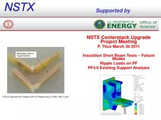
Post-Protection Current Transients in NSTX-CSU. Robert Woolley 2 June 2010. Mutual Inductance Dynamic Effects. Coil protection features must take into account anticipated coil current transients that occur after protection action is initiated.

E N D
Post-Protection Current Transients in NSTX-CSU Robert Woolley 2 June 2010
Mutual Inductance Dynamic Effects • Coil protection features must take into account anticipated coil current transients that occur after protection action is initiated. • Post-protection action current transients in PF and OH coils result from mutual inductance coupling • From a disrupting plasma toi the PF/OH coils • Between the PF/OH coils, thus linking their resistance dissipation effects • Eddy currents in passive structures provide shielding that affects time constants of coupling
Status -analysis of transients • Previous analysis updated • Corrected sign error PF4&5 currents • Improved resistance estimates • Conservative scan shows overshoot issues limited to PF1A, PF2, PF4 • Actual cases show some, but not much, overshoot • Result not yet conclusive, but indicate that post-protection-action current transients will not be a show-stopper
Conservative Current Bounds • Yellow=required plasmas • Orange (outside)=includes disruption • (Eddy currents in passive structure not included.) • White (middle)=current magnitude can increase by coupling to other decaying coil currents within orange range. • Red=10% past normal range
Finding Overshoot Cases • A simulation was set up to predict the current transients assuming • A specified set of initial coil currents • A 2 MA full plasma disruption occuring instantaneously at t=0. • A Level 1 Fault Protective action at t=0 shorts all PF and OH coil circuits. • Estimated circuit resistance values. • Calculate PF/OH/Plasma inductance matrix and series DCCLRs. • Using this simulation, most initial conditions do not result in currents exceeding normal range • However, some do. E.g., he very first plasma case listed in design spreadsheet overshoots some
Equilibrium #1 • The first required design point plasma equilibrium has PF1A at -6.5 kA. A 2 MA plasma disruption drives it beyond the yellow, and subsequent coupling to other decaying coil currents drives it a bit more. • PF4 is also driven beyond its normal limits
PF4 reaches +11.3 kA • Note that inclusion of eddy currents may reduce this calculated peak current
Conclusion • Previous concerns about transient post-protection currents were overstated due to acurrent range sign error; with corrections the overshoot issue is less significant. • Conservative bounds are too conservative. Need to search through initial condition space (Monte Carlo) to find limiting cases. • Search will be done with passive structure included. • Expect results will allow use of a very simple algorithm in the real-time protection.