Download
1 / 18
400 likes | 1.21k Views
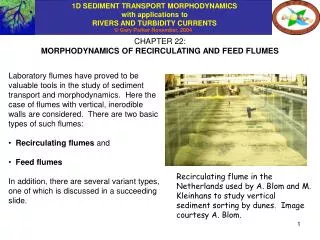
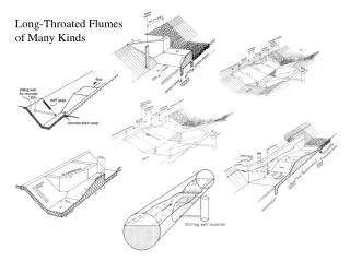
MEASURING FLUMES. By CH. VENKATARAMAIAH. CUTTHROAT FLUME. Flow measurement structures Weirs Drops V notches Cutthroat flumes Rectangular throat flumes Standing wave flumes Parshall flumes. General Cutthroat flume consist of converging section and diverging section

E N D
MEASURING FLUMES By CH. VENKATARAMAIAH
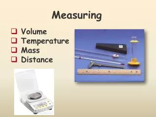
Flow measurement structures • Weirs • Drops • V notches • Cutthroat flumes • Rectangular throat flumes • Standing wave flumes • Parshall flumes
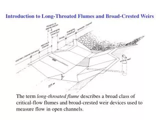
General • Cutthroat flume consist of converging section and diverging section • It has flat bottom and vertical walls. • Angle of convergence is 3:1 and angle of divergence is 6:1 • Convergence part consist of 1/3 length of flume • Divergence part consist of 2/3 length of flume • Ratio of upstream depth of flow to length of flume • should be equal to or less than 0.4 for accuracy. Single reading of upstream depth of flow to be taken at a distance of 2L/9 from the neck for free flow condition. D/S reading at a distance of 5L/9 from the neck is also required for submerged flow condition.
Design Procedure • Data: • Max. discharge = Q in cumec • Max. D/S flow depth = hb in m • Head loss = f in m • Max U/S flow depth = ha = hb + f in m • Length of flume = L in m • Throat width = W in m
Design for free flow condition • Read value of transition submergence (St) in percentage from figure 3. • Work out ratio (hb / ha ) x 100 (percent). If it is more than St, the flow is free • Qf= free flow discharge in cumec • Cf = free flow coefficient • hf = upstream flow depth in m • nf = free flow exponent • Kf= free flow flume length coefficient • Wf = throat width in m. • Qf = Cf(ha)nf • Cf = Kf W1.025 • If value of Qf as calculated is equal to or more than the required discharge, the result is OK. Otherwise, the variable parameters have to be changed till the required result is obtained.
Design for submerged flow condition The flume is designed for the submerged flow condition using the following equation: Qs = Cs (ha – hb)nf (- log St)ns Where Qs = submerged flow discharge in cumec ha = upstream flow depth in m hb = downstream flow depth in m Cs = submerged flow coefficient = Ks. W1.025 nf = free flow exponent ns = submerged flow exponent St = transition submergence Ks = submerged flow flume length coefficient St, nf , ns and Ks can be read from the graph in figure 3. The discharge Qs under submerged condition can be calculated for any combination of values of ha and hb using the above equation.
(1)Discharge Q = 2/3 (2/3.g)1/2 x Cfx Bt x H3/2 =1.075 Cf Bt H3/2 Bt = throat width in m H = d1 – Z + v2/ 15.2 d1 = depth of canal flow z = height of hump over canal bed v = velocity of canal flow. Cf = coefficient of friction Value of Cf Discharge 0.97 0.05 to 0.3 cumec 0.98 0.3 to 1.5 cumec 0.99 1.5 to 15 cumec 1.00 > 15 cumec For satisfactory functioning of standing wave flume, the ratio D2/ D1 should not be less than 0.50 D1 = U/S depth of flow over sill of throat D2 = D/S depth of flow over sill of throat The gauge (stilling) well for measurement of depth of flow in the canal should be located in the straight portion of the canal at a distance of 4 times the maximum head over the sill of the flume on the upstream side, measured along the axis of canal.
(2) Height of hump It is required to provide a hump in the canal to maintain proportionality between the rate of change of depth of flow over sill of the throat and the rate of change depth of flow in the canal. Where Z = height of hump d1 = depth of flow in the canal D1 = u/s depth of flow over the sill of throat m = any particular fraction of discharge x = approach channel index (varies from 1.5 to 2) Discharge equation of the approach channel is given by: Q = C1 d1x Discharges Q1,Q1',Q1'',Q1''', etc are worked out for the flow of depths of d1,d1', d1'',d1''', etc respectively and the value of x in the equation is estimated by least square method by considering these sets of d1 and corresponding Q. ∑ log Q . Log d1 - (∑ log Q ) ( ∑ log d1 ) x = M ∑ ( log d1)2 - ( ∑ log d1)2 M Where M is the no. of sets.
(3) Head loss: The head loss consists of the losses in: (i) Approach transition (ii) Exit transition (iii) Friction in structure (iv) Hydraulic jump Loss in transitions depends on the amount of fluming and its gradualness. The friction loss is usually small. The loss in hydraulic jump is given by the equation: HL = (d2 – d1)2 4 d1 d2 Where d1 = depth of flow before jump d2 = depth of flow after jump
(4) Approach transition : The radius of walls of the bell mouth entrance should be 3.6 H 1.5 starting from the throat. If ‘H’ is less than 0.30m, the radius may be 2H. Curvature (formed from the throat) should continue till it subtends an angle of 600, from where, it should be continued tangentially to meet the side of the channel. The bed convergence should begin on the same cross section as the side convergence. The radius of curvature of hump in the bed should be: rh = L12 + Z2 2 Z Where rh = radius of curvature of hump L1 = length between the junction of side wall with the bed of U/S channel and U/S end of throat along the axis of channel. Z = height of hump.
(5) Throat: • Sides of throat should be vertical and length should be 2.5 H. • Width of throat should be calculated from the discharge formula in sheet 2. • (6) Downstream glacis • The length of downstream glacis should be equal to 4H. • Side walls should be of same length. • Slope of the glacis is usually 1 in 20 or flatter. • Divergence of side walls to be 1 in 10 or flatter, so as to make the width at the toe of the glacis equal to or less than the downstream canal bed width.