Download
1 / 27

E N D
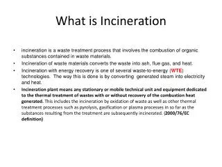
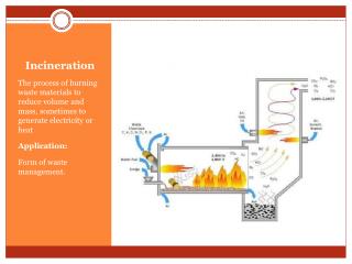
Oxidation systems are used to destroy organic compounds classified as volatile organic compounds (VOCs) and/or air toxic compounds. At sufficiently high temperatures and adequate residence times, essentially all organic compounds can be oxidized to form carbon dioxide and water vapor. The oxidation products of organic compounds containing chlorine, fluorine, or sulfur are HCl, HF, Cl2 or SO2. Source: USEPA, APTI415 : CONTROL OF GASEOUS EMISSIONS
High-Temperature, Gas-Phase Oxidation Processes • Recuperative (恢復式) thermal oxidizers : • Regenerative (蓄熱式) thermal oxidizers • Process boilers used for thermal oxidation Catalytic Oxidation Processes • Recuperative catalytic oxidizers • Regenerative catalytic oxidizers Flares used for thermal oxidation Source: USEPA, APTI415 : CONTROL OF GASEOUS EMISSIONS
High-temperature, gas-phase oxidation processes use temperatures in the range of 1,000°F to 2,000°F (540°C to 1,100°C). Thermal oxidizers and process boilers handle gas streams with inlet organic vapor concentrations less than 25% to 50% of their Lower Explosive Limit (LEL). Catalytic oxidation processes operate at temperatures ranging from 400°F to 1,000°F (200°C to 540°C) and are designed for gases containing less than 25% of the LEL. Flares are used for the combustion of organic vapor waste streams that have concentrations greater than 100% of the Upper Explosive Limit (UEL). Source: USEPA, APTI415 : CONTROL OF GASEOUS EMISSIONS
The terms recuperatorand regenerator refer to the type of heat exchanger used to increase system efficiency. A recuperator is a tubular or plate heat exchanger where heat is transferred through the metal surface. A regenerator uses a set of refractory packed beds that store heat. Both types reduce the amount of supplement fuel needed to oxidize the contaminants in the combustion chamber. With sufficiently high organic concentration, the energy released during oxidation may be sufficient to maintain the necessary temperature without the addition of supplemental fuel. Source: USEPA, APTI415 : CONTROL OF GASEOUS EMISSIONS
3 T’s • A proper oxidizer design is achieved by considering the three “Ts” of combustion—time, temperature, and turbulence. • Large residence times, high temperatures, and highly turbulent flow all contribute to the complete destruction of the organic pollutant. Source: USEPA, APTI415 : CONTROL OF GASEOUS EMISSIONS
Thermal oxidizer using multi-jet burners and baffles to promote mixing. Source: USEPA, APTI415 : CONTROL OF GASEOUS EMISSIONS
Oxidizer equipped with a double-pass recuperative heat exchanger. Source: USEPA, APTI415 : CONTROL OF GASEOUS EMISSIONS
Flowchart of a recuperative heat exchanger. Source: USEPA, APTI415 : CONTROL OF GASEOUS EMISSIONS
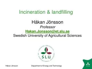
Regenerative thermal oxidizers • Regenerative thermal oxidizers have heat recovery efficiencies as high as 95%, much higher than recuperative units. Because of the high inlet gas temperatures created by the heat recovery, burner fuel is required only if the organic vapor concentrations in the gas stream are very low. At moderate-to-high concentrations, the heating value of the organic contaminants is sufficient to maintain the necessary temperatures in the combustion chamber. • High-efficiency heat recovery is achieved by passing the inlet gas stream through a large packed bed containing ceramic packing that has been previously preheated by passing the outlet gases from the combustion chamber through the bed . • At least two beds are required, and gas flow dampers are used to switch the inlet and outlet gas streams to the appropriate beds. • Three beds are commonly used in a regenerative system. One of the beds is used to preheat the inlet gas stream, the second is used to transfer the heat of combustion from the treated gas stream, and the third is in a purge cycle. Without a purge cycle, emission spikes would occur as a portion of the untreated gas stream would be released immediately after each flow reversal. Source: USEPA, APTI415 : CONTROL OF GASEOUS EMISSIONS
Source: http://www.thecmmgroup.com/custom-designed-regenerative-thermal-oxidizer-rto
Regenerative thermal oxidizer. Source: USEPA, APTI415 : CONTROL OF GASEOUS EMISSIONS
Flameless thermal oxidizer. Source: USEPA, APTI415 : CONTROL OF GASEOUS EMISSIONS
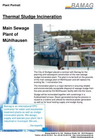
Process Boilers Used for Thermal Oxidation • An alternative to installing a thermal oxidizer is to burn the waste gases in an existing plant or process boiler, thus avoiding the capital cost of new equipment. • Process and plant boilers are normally designed to operate with combustion chamber temperatures in excess of 1,800°F (980°C) and with flue gas residence times in excess of 1 to 2 seconds, conditions similar to those of thermal oxidizers. • The waste gas stream is usually injected into the boiler at an elevation close to the main burners and overfire air nozzles. In some cases, the waste gas stream may be used as part of the combustion air supply for the burners in the boiler. Source: USEPA, APTI415 : CONTROL OF GASEOUS EMISSIONS
Oil-fired boiler. Source: USEPA, APTI415 : CONTROL OF GASEOUS EMISSIONS
Cutaway of a catalytic oxidizer. Source: USEPA, APTI415 : CONTROL OF GASEOUS EMISSIONS
Flares Used for Thermal Oxidation • Flaring is used for the destruction of intermittent or emergency emissions of combustible gases from industrial sources that otherwise would create safety and health hazards at or near the plant. • Flares are elevated to eliminate potential fire hazards at ground level. Ground-level flares must be completely enclosed to conceal the flame. Either type of flare must be capable of operating over a wide range of waste gas flow rates in order to handle all plant emergencies. • Flares are usually used for waste gas streams having organic vapor concentrations above the upper explosive limit. The heat content of the organic compounds in the waste gas stream must usually be in the range of 100 Btu/SCF to 150 Btu/SCF to sustain efficient combustion; otherwise supplemental fuel must be added. This type of system is referred to as a fired or endothermic flare. Source: USEPA, APTI415 : CONTROL OF GASEOUS EMISSIONS
Although the flares are designed to eliminate waste gas stream disposal problems, they can present safety and operational problems of their own. • Thermal radiation. Heat given off to the surrounding area may be unacceptable. • Light. Luminescence from the flame may be a nuisance if the plant is located in an urban area. • Noise. Jet venturis are used for mixing at the flare tip. They can cause excessive noise levels in nearby neighborhoods. • Smoke. Incomplete combustion can result in toxic or obnoxious emissions. • Energy consumption. Flares waste energy because of (1) the need to maintain a constant pilot flame and (2) the loss of the heating value of the chemicals burned. Source: USEPA, APTI415 : CONTROL OF GASEOUS EMISSIONS
Elevated Flares • A typical elevated flare is composed of a system that first collects the waste gases and then passes the gases through a knockout drum to remove any liquids. • Flame arrestors are placed between the knockout drum and the flare stack to prevent flashback of flames into the collection system. • The elevated flare stack is essentially a hollow pipe that may extend to heights exceeding 150 feet. The diameter of the flare stack determines the volume of waste gases that can be handled. • The smokeless flare tip using steam injection is at the top of the stack. It is comprised of the burners and a system to mix the air and fuel. • Steam jets have proven to be one of the most effective ways to mix air and waste gases. In addition to increasing turbulence, the steam reacts with the gases to produce oxygenated intermediate compounds that burn readily at lower temperatures and reduce polymerization of organic compounds in the waste gas stream.
http://upload.wikimedia.org/wikipedia/commons/3/3c/Shell_haven_flare.jpghttp://upload.wikimedia.org/wikipedia/commons/3/3c/Shell_haven_flare.jpg
Steam-assisted Elevated Flare System. Source: USEPA, APTI415 : CONTROL OF GASEOUS EMISSIONS
Source: http://en.wikipedia.org/wiki/File:FlareStack_System.png
Smokeless flare tip of an elevated flare. Source: USEPA, APTI415 : CONTROL OF GASEOUS EMISSIONS
Enclosed ground flare. Source: USEPA, APTI415 : CONTROL OF GASEOUS EMISSIONS
Biofilter system Source: USEPA, APTI, 2002, Sources and Control of Volatile Organic Air Pollutants
Biotrickling filter system Source: USEPA, APTI, 2002, Sources and Control of Volatile Organic Air Pollutants
Bioscrubber system Source: USEPA, APTI, 2002, Sources and Control of Volatile Organic Air Pollutants