Download
1 / 22
230 likes | 583 Views
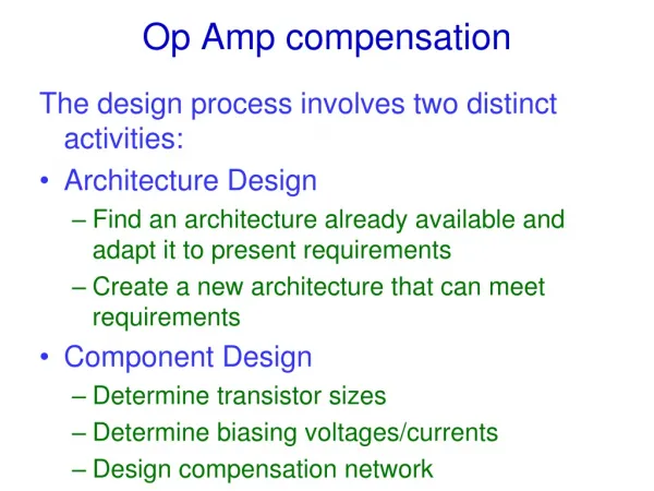
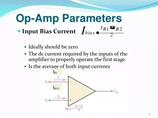
Op Amp Applications. Analyses for A ∞ and loop gain are separate. Design breaks down into two parts: Arranging A ∞ to do the job Ensuring the feedback loop has enough loop gain and is stable. Here we focus on the A ∞ part, assuming you already know how to get a stable feedback loop.

E N D
Op Amp Applications Analyses for A∞ and loop gain are separate. • Design breaks down into two parts: • Arranging A∞ to do the job • Ensuring the feedback loop has enough • loop gain and is stable. • Here we focus on the A∞ part, assuming you • already know how to get a stable feedback loop. EEE 3308
Rin vo vs Rout Non-Inverting Amp Ideal for Voltage Amp R2 R1 EEE 3308
Rin vo vs Rout Non-Inverting Amp Ideal for Voltage Amp R2 R1 Voltage Follower Rin vo vs Rout Ideal Voltage Buffer Inverting Amp with R1 → ∞ EEE 3308
Rin vo vs Rout Voltage Follower Ideal Voltage Buffer In what sense is this “ideal”? EEE 3308
Rin vo vs Rout Voltage Follower Ideal Voltage Buffer In what sense is this “ideal”? RS Adding RS, RF or RL reduces T but has no effect on A∞. Still A∞ = 1. vo vs RL RF EEE 3308
R2 Rin R1 vo Inverting Amp vs Ideal for Voltage Amp Rout EEE 3308
R2 Rin R1 vo Inverting Amp vs Ideal for Voltage Amp Rout R2 RS R1 vo vs EEE 3308
R2 Rin R1 vo Inverting Amp vs Ideal for Voltage Amp Rout R2 R1 On the other hand, adding RA, RB or RC reduces T but has no effect on A∞ = -R2/R1 vo RA vs RC RB EEE 3308
R1 R2 v1 Summing Amp R2 v2 . vo . . Rn vn T decreases with n: EEE 3308
R2 Rin I to V Converter/ Transimpedance Amp vo Ideal for Transimpedance Amp (iin, vout) is Rout EEE 3308
Current-Mode Outputs:Put load in series with thefeedback signal path vs io R2 Rout R1 EEE 3308
V to I Converter/Transadmittance Amp Rin Ideal for Transadmittance Amp (vin, iout) vs io R2 Rout R1 EEE 3308
V to I Converter/Transadmittance Amp RA RB vs RA, RB, RC, and RD reduce T but do not affect A∞ = 1/R1 io RC R2 R1 RD EEE 3308
io Current Buffer Rin R2 Ideal for current in current out Rout is EEE 3308
Current Amplifier io RL R2 is R3 EEE 3308
Current Amplifier io v3 virtual ground RL R2 is R3 EEE 3308
Current Amplifier io v3 RL R2 is R3 i3 EEE 3308
Current Amplifier io v3 RL R2 is R3 i3 EEE 3308
Current Amplifier io v3 RL R2 is R3 i3 EEE 3308
Current Amplifier io RL R2 is R3 EEE 3308
RA RO Current Amplifier io RB RL R2 RC RS is R3 Adding RA, RB, RC, RS, or RO reduces T but has no effect on A∞ EEE 3308
Current-Mode Outputs:Put load in series with thefeedback signal path vs io RLoad R1 Later we’ll see that there is a different way to take current-mode outputs from a feedback circuit using transistors. EEE 3308