Download

1 / 21
210 likes | 557 Views
What does Heterodyning mean? . Heterodyning is the process where two frequencies are mixed in order to produce secondary frequencies that are exactly the sum and difference (absolute value) of the original two frequencies. Typically, the difference in the frequencies is referred to as the beat" f

E N D
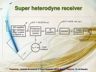
1. Building a Super-Heterodyne Receiver to Observe the 21 cm Line Ted Jaeger
Advisor : Dr. Robert Mutel
2. What does Heterodyning mean? Heterodyning is the process where two frequencies are mixed in order to produce secondary frequencies that are exactly the sum and difference (absolute value) of the original two frequencies.
Typically, the difference in the frequencies is referred to as the �beat� frequency
3. What is Super-heterodyne? Why not analyze the signal directly? Super-heterodyning is a process that selects only the beat frequency in order to reduce the frequency of source signal.
Reducing the frequency of the source signal allows you move the signal into a frequency range that the test equipment might be better designed to operate in.
4. How does Super-heterodyning Work?
5. e-SRT Design Goals Reduce a 1420.358 MHz (21 cm) signal to 1 MHz (in the center of a 2 MHz window)
Build a system with low noise
Create a �Teaching Device� vs. a �Black Box�
6. e-SRT Design Antenna and Front End Box
IF Module
IF Converter
7. Front End Box New design contains components to measure system temperature and functionality
Calibrated 50 ohm Load
Broadband Noise Diode
Test Signal Input from Control Room
9. IF Module Once the signal leaves the Front End Box, the process of Super-heterodyning begins.
Design contains signal test points to view the down-converting
11. Path of a Test Signal
12. Path of a Test Signal
13. Path of a Test Signal
14. Path of a Test Signal
15. Path of Test Signal For the last signal conversion, a different type of mixer must be used
16. Single Side Mixers Super-heterodyning reduces the input signal by mixing with the LO signal, regardless of which side of the LO the input is located.
17. Single Side Mixers Single Side Band Mixers filter out either the LSB or the USB before creating the beat frequency
18. Path of a Test Signal A test signal of 1420.358 MHz maps to an output signal of 1 MHZ
Signals between 1395.358 MHz and 1445.358 MHZ also map into this window
19. Work Needed to be Done Autocorrelation
Interface
21. System Temperature It is useful the characterize the noise in the e-SRT system in units of Temperature
For any radiating object, regardless of the source of radiation, the power observed can be characterized by a �Brightness Temperature�
The System Temperature, along with the fixed dimensions of the telescope define what sources can be reliably observed
22. System Temperature The e-SRT has a SNR defined as follows:
Then, for an integration time t fixed at 0.5 seconds, a system sensitivity x approx. 780 Jy/K, a bandwidth of 2 MHz and a SNR of 5 yields ...