Download
1 / 17
170 likes | 278 Views
The XV th International Workshop on Polarized Sources, Targets and Polarimetry (P S TP 2013). University of Virginia, Charlottesville, VA, USA September 9 - 13, 2013. Ion Polarization Control in MEIC Rings Using Small Magnetic Field Integrals

E N D
The XVth International Workshop on Polarized Sources, Targetsand Polarimetry (PSTP 2013) University of Virginia, Charlottesville, VA, USA September 9 - 13, 2013 Ion Polarization Control in MEIC Rings Using Small Magnetic Field Integrals Ya.S. Derbenev 1, F. Lin1, V.S. Morozov 1, Y. Zhang 1, A.M. Kondratenko 2,M.A. Kondratenko 2 and Yu.N. Filatov 3,4 1 Jefferson Lab, Newport News, VA 2Science and Technique Laboratory Zaryad, Novosibirsk, Russia 3Joint Institute for Nuclear Research, Dubna, Russia 4Moscow Institute of Physics and Technology, Dolgoprydny, Russia
Outline • Introduction • Polarization preservation during acceleration in the pre-booster and large booster • Deuteron polarization control scheme with “small” solenoids for the collider • Proton polarization control with “small” radial fields in the collider • Compensation of the 0th harmonic of the spin perturbation in the collider ring. Spin response function and its suppression in the interaction points. • Conclusions
Prebooster Ion source Warm large booster (up to 20 GeV/c) Three Figure-8 rings stacked vertically SRF linac Cold 20-100 GeV/c proton collider ring Warm 3-12 GeV electron collider ring Medium-energy IPs with horizontal beam crossing Injector 12 GeV CEBAF Schematic Layout of Medium-Energy Electron-Ion Collider (MEIC) at Jefferson Lab
Cooling Cooling to high-energy collider ring SRF linac Ion source Prebooster (accumulator ring) Medium-energy collider ring Large booster Major Components of MEIC Ion Complex The MEIC ion beam polarization design requirements are: • High polarization (over 70%) for protons or light ions (d, 3He++, and possibly 6Li+++). • Both longitudinal and transverse polarization at all IPs. • Sufficiently large lifetime to maintain high beam polarization. • Spin flipping at a high frequency.
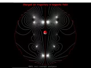
n = 0 Spin Motion in “Figure-8” Rings • The figure-8 structure provides unique capabilities for manipulating the beam polarization • In an ideal structure (without perturbations) all solutions are periodic • It has an energy-independent (zero) spin tune • It allows control of the beam polarizationwithsmall fields without orbit perturbation • Iteliminates depolarization problem during acceleration • It becomes possible to efficiently control the polarization of a beam of particles with any anomalous magnetic moment including particles with small anomalous moments, such as deuterons • Makes possible ultra-high precision experiments with polarized beams
Control of Polarization during Acceleration The polarization is stable if n>>w0 (w0 is the «zero» spin resonance strength) B||L of only 3 Tm provides deuteron polarization stability up to 100 GeV. A conventional ring at 100 GeV would require B||L of 1200 Tmor BLof 400 Tm.
Acceleration and Spin Matching in MEIC Conventional ~20 GeV accelerators require
Control of Deuteron Polarization in Collider Ring A scheme for obtaining any polarizationdirection Beam injected longitudinally polarized, accelerated and then desired spin orientation adjusted are the spin rotation angles in the solenoids is the spin rotation angle between the solenoids is the orbit rotation angle between the solenoids is the angle between the polarization and velocity directions
(B||L)1 (B||L)2 Control of Deuteron Polarization in Collider Ring (B||L)1,2(Tm) vs. p(GeV/c) longitudinal polarization radial polarization
(BxL)1 (BxL)2 (BxL)3 (BxL)4 Control of Proton Polarization in Collider Ring Last two arc dipoles (BL)i(Tm) vs. p(GeV/c) longitudinal polarization radial polarization
Control of Proton Polarization in Collider Ring Vertical excursion of the reference orbit
Spin Response Function • Zero-harmonic spin resonance strength can be calculated using spin “response function” • Response function is determined by the accelerator’s design lattice and represents the spin response to a-function perturbation at an azimuthal angle : • Such a dipole generates the following strength of the zero-harmonic resonance: • For a flat figure-8 orbit, the response function is given by where is the spin rotation angle in the collider’s bending dipoles, is the Floquet function are the vertical betatron function and betatron tune
Response Function in Collider Ring is the periodic response function describing effect of any radial fields and allowing one to calculate the zero-resonance strength. IP IR Highest error sensitivity in the IR’s but error control requirements high anyway for dynamic reasons. IP
Response Function and Zero Spin Resonance Strength • The total zero-harmonic resonance strength: • is composed of • coherent part due to closed orbit excursion • due to transverse and longitudinal emittance • The coherent part • arises due to radial fields from • dipole roll • vertical quadrupole misalignment
Compensation ofZero-Harmonic Spin Resonance Strength • In the linear approximation, the zero-harmonic spin resonance strength is determined by two components of the spin perturbation lying in the ring’s plane: and can be compensated by correcting devices whose spin rotation axis lies in the same plane insertion for spin control insertion for strength compensation insertion for strength compensation insertion for spin control • With compensation of the “coherent” component of the spinresonance: 15
Conclusions • Schemes were developed for MEIC figure-8 rings that • eliminate depolarization problem during acceleration • allow control of the beam polarization with small fields without significant orbit perturbation • efficiently control the polarization of particles with any anomalous magnetic moment including those with small anomalous moments, such as deuterons • allow adjustment of polarization orientation in either of the two straights • allow single-turn as well as multi-turn spin-flipping schemes • make possible ultra-high precision experiments with polarized beams • Future plans • optimization of the developed schemes • integration into the ring lattices • validation by spin tracking • development of spin-flipping techniques