Download
1 / 32
360 likes | 602 Views
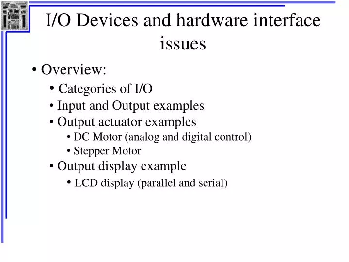
I/O Devices and hardware interface issues. Overview: Categories of I/O Input and Output examples Output actuator examples DC Motor (analog and digital control) Stepper Motor Output display example LCD display (parallel and serial). I/O Categories. Input devices Sensors, User-input

E N D
I/O Devices and hardware interface issues • Overview: • Categories of I/O • Input and Output examples • Output actuator examples • DC Motor (analog and digital control) • Stepper Motor • Output display example • LCD display (parallel and serial)
I/O Categories • Input devices • Sensors, User-input • Output devices • Actuators, Displays • Complex I/O devices (printers, faxes, coprocessors, etc) Analog I/O Digital I/O • Voltage levels - Voltage levels • Current draw - Synchronization • Sampling frequency - Throughput • Noise - Noise
Sensors light force sound position orientation proximity tactile temperature pressure humidity speed acceleration displacement User input keyboards joysticks mouse keypad switches touchpad dial slider Input Examples
Actuators motors solenoids relays heaters lights piezoelectric materials (buzzers, linear actuator) speakers Displays LED displays LCD displays CRT displays indicator lights indicator gauges Output Examples
Example – DC Motor • Important in LOTS of applications • cameras, drives, elevators, trains, robots… • Many types, but all work similarly: • Apply voltage across + and – leads, electrical energy is converted to mechanical energy. • For some range of voltage, the torque of the motor shaft is proportional to value of voltage.
DC Motor • Current required by motor depends on how it is loaded. • Current is almost always more than the uC can provide. • Need an interface circuit between uC and motor. Motor current (A) stalled loaded no load Applied voltage (volts)
Interfacing MotorsDigital Outputs • Basic idea is to use a switch of some kind to isolate current in uC from motor current. • Motor is an inductor though, so it stores current. • Flyback diode used to route current away from switch when switch opens to avoid damage to switch. flyback diode External Voltage + switch open current switch closed current motor Control signal from uC
Interfacing MotorsDigital Outputs H-Bridge – circuit topology that allows bi-directional control of motor. • Each switch controlled by an output of the uC. • Switches implemented by relays, solid-state switches, or transistors • Diodes omitted for simplicity. + external voltage - motor
Interfacing MotorsAnalog Output • 8051 DAC can provide up to 15 mA of current, up to 3.3V voltage. • Must provide both voltage and current amplification to drive a DC motor. • Amplifiers • Power MOSFETs • Motor driver ICs • Relays
Robo51 DC Motors Duty Cycle = Ton / (Ton+Toff) Average Motor Voltage: Vm = Supply Voltage X Duty Cycle
16-bit PWM Mode match causes output to go high overflow causes output to go low
16-bit PWM Mode • Produces a signal with a variable pulse width. PCA0=FFFF PCA0 overflow (CF) interrupt low time set by PCA0CP PCA0=PCA0CP CCFn (compare match) interrupt Note: Both CCFn and CF (counter overflow) cause ISR at 4Bh to execute if enabled.
16-bit PWM Mode • To vary the period of the waveform, change the reload value of PCA0 on overflow. • To vary duty cycle, write new value to PCA0CPH and PCA0CPL • Writes should be synchronized with CCF. • When writing a 16-bit value to the PCA0 Capture/Compare registers, the low byte should always be written first.
Stepper Motors • Inherent digital interface • Can easily control both position and velocity • Used in disk drives, printers, etc. • Small, fixed rotation per change in control signals
S1 Basic Operation • Simplified stepper motor 5 “teeth” 360 5 = 72 moves 72 per “step” Changing polarity of stator magnets causes step. Typical stepper motors have 200 steps per revolution, with 1.8 per step. - phase 2 + S5 N5 N1 + phase 1 - S4 N4 N2 S2 S3 N3 rotor electromagnets stator
Stepper Motor Interface +Vmotor VDD 4-phase stepper motor Inverting buffers 8051 A A’ B B’ port pins 1010 1001 0101 0110 1010 1.8 1.8 1.8 1.8
Output Display Example: LCD Display • LCD – Liquid Crystal Display • Lower power than LED display • More flexible in size and shape • Slower response time
LCD Operation • AC voltage required – DC voltage damages LCD • Control changes reflectivity of the liquid crystal material. • Actual light energy supplied by room light or back light. front plane CMOS back plane control 60 Hz Oscillator liquid crystal material
LCD Interfacing • Simple parallel interface – similar to LED: VDD 7-segment LCD Driver/Decoder Separate Front Planes 8051 a b c d e f g A B C D port pins Common Back Plane 60 Hz Oscillator
LCD Interfacing • Serial driver interface MC145000 LCD Driver data in data out 48 bit shift register clock 48 bit latch register BP1 BP2 BP3 BP4 FP1 FP2 FP3 FP4 FP5 FP6 FP7 FP8 FP9 FP10 FP11 FP12 48 segment LCD display
Using Microcontrollers for Control • Overview • Open-loop control systems • Simple closed-loop control systems • Closed-loop position control • PID controllers
Open-loop Control Systems • No feedback path from the plant Real control variables X(t) Driving Forces V(t) Control commands U(t) Desired control variables X*t Physical Plant Actuators uC
Open-loop Control Example • Stepper motor Real control variables X(t) Driving Forces V(t) Control commands U(t) Desired control variables X*t Physical Plant Actuators uC Inverting driving buffers desired shaft position specified in program stepper motor uC shaft position
Open-loop Control Example • Traffic light controller Inverting driving buffers uC desired light pattern in software
Closed-loop Control • Feedback from plant to controller Real control variables X(t) Driving Forces V(t) Control commands U(t) Desired control variables X*t Physical Plant Actuators uC Sensor
Closed-loop Control“Bang-bang control” • Bang-bang – control output can only turn something ON or OFF. No variable control. • Requires a “deadband” or “hysteresis” which defines a range of acceptable values for output - otherwise the control system components can wear out from too many switching cycles. (Relays, for example, have a limited lifetime). • Works well with physical plant with a slow response time.
Closed-loop Control Systems • Bang-bang control – temperature control example. Desired temperature, Tlow < T < Thigh “plant” Flowchart of control algorithm Heater estimate T’ uC T’ > Thigh T’ < Tlow T’ T’ Temperature sensor Leave Turn on Turn off
Closed-loop Position Control • Incremental control – adds or subtracts a small constant from the output control command, U(t), in response to X(t) sensed. Real control variables X(t) Driving Forces V(t) Control commands U(t) Desired control variables X*t Physical Plant Actuators uC +1 or -1 Sensor
Closed-loop ControlPID Controller • Faster and more accurate than previous systems. • Based on linear control theory. • Three components – sometimes fewer are used. • Proportional – output is linearly related to error signal. • Integral – output is related to integral of the error signal. • Derivative – output is related to derivative of the error.
PID Controller • To understand, must transform parts of control diagram into discrete time domain. • Very important to have periodic sampling and processing. • In the figure below, n is the sample number Real control variables x(t) Desired output x* + e(n) uC PID controller Physical Plant u(n) p(t) Actuator - x’(n) Sensor error signal: e(n) = x*(n) - x’(n)