Download
1 / 46
480 likes | 1.03k Views
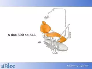
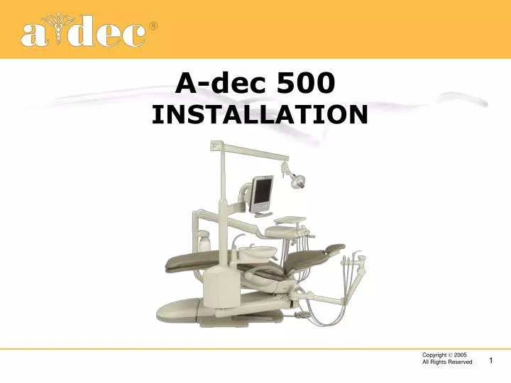
A-dec 500 INSTALLATION. A-dec 500 Installation. Objectives: To make your installation: Better, Faster, Easier, Safer. A-dec 500 Installation. Refer to the A-dec 500 Installation Guide 86.0400.00 Page ii Equipment Installation Box 1: Chair (Install Guide)

E N D
A-dec 500 Installation Objectives: To make your installation: • Better, • Faster, • Easier, • Safer.
A-dec 500 Installation • Refer to the A-dec 500 Installation Guide 86.0400.00 • Page ii • Equipment Installation Box 1: Chair (Install Guide) Box 2: Front Mount (contains box 4 for floor box when delivery system is ordered) Box 3: Delivery System Box 5: Support Link Box 6: Assistants Instrumentation Box 7: Lower Arm Box 8: Support Center Box 9: Monitor Mount Box 10: Light
A-dec 500 – 1 Package – 10 boxes Box 1: Chair (Install Guide) Box 2: Front Mount (contains box 4 for floor box when delivery system is ordered) Box 3: Delivery System Box 5: Support Link Box 6: Assistants Instrumentation Box 7: Lower Arm Box 8: Support Center Box 9: Monitor Mount Box 10: Light
A-dec 500 Installation Tips • Be familiar with the all-in-one Installation Instructions 86.0400.00 • Retain with equipment or for future • Numbered boxes: • Indicate the sequence of installation • Allow you to stage equipment • Inventory the modules before starting the install • Full size templates are available parts book p.2: • A-dec 500 Product 86.0904.00 • 511 Chair 86.0905.00 • Floor box 85.0472.00 • Checklist Review
A-dec 500 Installation Tips • Tools Recommended: • Sizes are all SAE, no metric • Hex Key Set (inch) • Phillips & standard screw drivers • Socket wrench set (SAE) • Snap ring tool • Adjustable wrench • Needle nose pliers • Combination wrench set (SAE) • Standard pliers • Diagonal cutters • Hammer • Wire strippers • Level
A-dec 500 Installation Tips • Additional tools that might be helpful: • Chapman tool set • Taps and T handle • Other: • Tape • Extra cable ties • Paper towels or rags • Umbilical stringer (009.015.00) • A-dec Barbs and Fittings Kit (90.1021.00) • 5/16” barb fittings (023.814.01) • 5/16” Sleeves (025.109.00) • Dry Cartridges (38.1783.00) • Wet Cartridges (38.1780.00)
A-dec 500 Installation Tips • Be familiar with the Legris air tubing connectors • Ensure end is cut square • Push into connector fully • Pull on tubing to check grip on tubing • To release tubing from connector, push on outer ring while pulling tubing out • Leave service length to avoid side loading the fitting which could create an air leak • Currently used only on the new 5/16” size air tubing connections.
A-dec 500 Installation Tips • General • Managing Cords and Tubing • Route in spaces provided • Trim tubing to length • Cable tie cords and cables into neat coils • Covers have a low profile and must not have any interference to fit properly • Neatness counts!
A-dec 500 Installation Tips • General • CAUTION: Keep hands/fingers clear – this is a new chair with different pinch points to be aware of • Covers and Upholstery • Leave them off and set, safely, aside until the installation is complete
A-dec 500 Installation Tips • General • Start all the fasteners before tightening any • For example the 3 on the back support • Or the 2 button heads for mounting the Cam • Leveling • Rough – do this to maintain tension or prevent movement • Final – do this when the install is complete and the instruments installed
A-dec 500 Installation Tips • Chair (Box 1) • About the same size as Cascade • Chair box measures 48”L x 30”W x 31”H • Base plate is 26 3/4” W x 34 ½” L • Heavier by 100 lbs • Weight – 400 lbs (packaged) • Use assistance to move • Two people recommended • Dolly or hand truck
A-dec 500 Installation Tips • Chair strapped to Appliance Hand Truck • Leave the two shipping straps in position • Use care when going down or up curbs or steps • Balance carefully
A-dec 500 Installation Tips • Chair • Handholds on seat frame at front and rear • Be sure the shipping straps in place • Do not use the armrests
Moving the chair • Chair Lifter Tools • Support Link Handle • Bolts to support link mount • No P/N as yet • Seat Frame Handle • Schedule 80 PVC • Slides over seat frame • No P/N as yet NEW
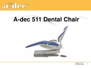
A-dec 500 Installation Tips • Full product dimensions are in the Equipment Catalog • 511 chair template available, order 86.0905.00 • Chair should be bolted to floor • Anchor kit 62.0193.00 included • Install Guide page 3
A-dec 500 Installation Tips • Chair • Shipping pin has tag to locate it • Release the swivel brake if the pin is difficult to pull out • Can be left in place to lock out chair swivel if desired • Retain for future use or chair movement. Bags tied to chair for pin and straps. • Power • Air/electric switch connection for Master ON/OFF • ON/OFF button for visual indication of mains power
A-dec 500 Installation Tips • Chair • 3 Tap Feature • Label on base plate • Be patient • Chair has a soft start feature so it seems slow to start moving (down) • Look for the relay LED on the PCB • PCB has test points to operate chair if needed. • Note: this will disable the 3 tap feature but it can be re enabled by cycling mains power
A-dec 500 Installation Tips • Front Mount (Box 2) • Locate hardware kit • Install the Leveling Cam • Raise back up • Raise seat frame up • Install 2 button head leveling cam screws finger tight • Install the 2 leveling studs until only 2 – 3 threads left
Front Mount Installation • Front Mount (Box 2) • The back needs to be full down or the mount will not go on • Tip assembly up to allow mount to hook over the cam • Rough level the front mount at this time using the cam and the 2 leveling studs • Secure the leveling stud flanged washers • Run in the 2 stabilizing screws against the upper structure. • Changed to grade 5 from grade 2 Oct ’04.
Water Bottle on Front Mount • Box 4 is in Box 2 if Delivery System is ordered • Water bottle • Floor box and utilities • Chair air/water manifold • Install the Cap Housing • Hole plug pops out easily when loosened from the bottom • Start button head cap screw for housing • Slide the housing down over the cap screw and tighten the screw • Route tubing through arm and retaining boss • Trim air and water tubing and connect to chair air/water manifold
Delivery System • Mounting the Unit (Box 3) • Lube post (LubriPlate) • Add thrust washer • Mount the Delivery System before routing the tubing and wiring • Install rotation stop ring and large snap ring (using your snap ring pliers) • Tension Adjustment • Use 3/32” hex wrench to add tension to delivery arm
Delivery System Tubing Sheath • Delivery System • Install the Spiral Sheath • Wait until all delivery system plumbing and wiring installed • Start near front and work it forward into the rigid arm • Delivery mount pan covers other end • Rotation stops can be set in front or rear holes depending on arm rotation • Foot Control Sheath • Ensure 1/8” tubings are up so they fit in strain relief correctly
Floor Box • Floor Box Carton (4) • Packaged with front mount inside box 2 or may be separate • Frame and cover • Flush or non flush mounted • 3 or 10 foot umbilical • Utilities • Air gauge is placed in slot in frame • Chair air/water manifold attaches to lift arm • Water bottle and cap assembly
Vacuum and Gravity Adapters • Gravity drain 023.812.000 • Vacuum Adapter 023.816.00 • More connectors in Parts book P/N 023.812.00 P/N 023.816.00
Water Bottle Installation • Lube o-ring on receptacle • Water Bottle - quick and easy installation • Align the bottle seam with the cap • Push the bottle straight up • Rotate bottle to the right (counter clockwise)
Support Link Installation • Support Link (Box 5) • Install leveling bar with dowel pins and leveling bolt • Install support link • Install the top 2 bolts to hold support link in position • Thread the leveling bolt into the support link and rough level • Use jamb nut to lock it against leveling bar • Lock in position with 4 bolts, tighten to 65 ft-lb • Protect the base plate with a piece of cardboard
Support Link Stop Switch • Stop switch assembly (Kit 43.0087.00) • Modify if Lower Arm is to be installed • Make electrical connection at chair stop switch • Mount lower arm to support link • Bearings for top and bottom are Teflon, no lube required • Tighten up on the lower arm set screw adjustment to level
Support Link Stop Switch • Install channel on under side of link • Install the lower arm air tubing in the channel • Install the actuator plates with the stand off screws
Lower Arm • Leveling Lower Arm • Lift end of arm while tightening the screw with a 3/16” hex wrench • Install end cap • Tuck end of stop tube in at bottom of arm
Solids Collector Installation • To Install/Remove the Solids Collector • Solids collector is keyed for removal and replacement • Rotate tubing inlets toward the chair backrest and lift the collector straight up
Drain and Vacuum Fittings • Durr fittings for Drain and Vacuum • Adaptors included to fit stub ups • 25mm (¾”) to ½” brass connector • Secure fit, barbed ends, o-ring seal, and they swivel • Red o-ring 035.053.01 • Lube with silicone grease • Blue retaining clip to secure each connection • Clip 022.090.00
Lift Arm Channel • Drain and vacuum tubing • Vacuum Tubing channel • On right side for the 25 mm vac • Drain Tubing channel • On the left side for the 20 mm drain • Wire clip retains tubing in lift arm channel • Lift arm slots to secure • Foot control • Data cables • Power cords
Hole for Monitor or Light • Knock out hole for monitor post • Don’t use hammer to knock out the hole, you could damage the top • Knock hole out from underneath prior to mounting housing on lower arm • CAUTION: Careful of sharp edges
Cuspidor • Cuspidor Installation • Leave tubing/cords cable tied • Place rotation stop on post and tighten • Place cuspidor on post, allow it to rest on the post box frame part way down • Route tubing/cord bundle through arm and into lift arm • Align cuspidor with arm and lower on to arm being careful not to impact stop ring
Water Bottle on Support Center • Remove cap assembly with 2 screws • Route tubing • Mount bottle housing on support center plate with the 2 screws • Trim tubing and connect to chair air/water manifold
Monitor Installation • Insert keyed trim ring • Insert keyed monitor post into support center • Install rotation stop ring • Install monitor rigid arm to post • Route power cord and video cable
Dental Light Installation • Chair Mounted Dental Light (Box 10) • Flex arm and head with power cord • Rigid arm • Lower straight post • Post adapter • Trim ring • Stabilization ring 28.1574.00 • Power cord extension
Dental Light Installation • Secure light post with screw through keyhole and into post, tighten firmly • Connect light power cord to extension cord in support arm and rout to power supply • Light flex arm and rigid arm need do not need to be lubricated, there is a Teflon bushing inside • Tighten screw to ensure they are locked together
Dental Light Installation • Tighten locking tab retaining screw to ensure ridged arm and flex arm securely locked together
A-dec 500 Installation • Don’t forget: • The delivery system thrust washer • To lube the water bottle o-ring • The cuspidor swivel stop
A-dec 500 Installation • Don’t forget: • The cuspidor trim ring, correctly fitted • The monitor mount rotation stop • The light trim ring
A-dec 500 Install Checklist • Why have one? • All items installed • Chair bolted to the floor • All items work • All Stop Switch functions • All items adjusted • All items programmed • Staff informed about equipment operation and maintenance • In-service clinic performed by dealer sales or technical rep
A-dec 500 Install Checklist • Checklist: • An aid to installation • A reminder for the installer • Retained for reference
A-dec 500 Installation Questions • Which box is the Installation Guide in? • Where is the Floor Box 4 when a Delivery System is included? • What should be the first item you look for in a box? • Where can the Water Bottle be installed? • Can the 3 tap feature be reactivated? How? • On which side of the lift arm does the drain tubing go?