Download
1 / 27
280 likes | 450 Views
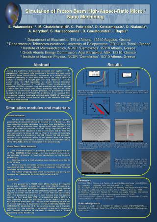
Simulation of Thermal Effects for the Analysis of Micro Laser Assisted Machining. By Saurabh R Virkar Under guidance of Dr. John A Patten ICOMM 2010 Venue: University of Wisconsin, Madison. Introduction:.

E N D
Simulation of Thermal Effects for the Analysis of Micro Laser Assisted Machining By Saurabh R Virkar Under guidance of Dr. John A Patten ICOMM 2010 Venue: University of Wisconsin, Madison
Introduction: • Silicon Carbide (SiC) is an advanced engineered ceramic and an alternative to semiconducting Silicon (Si) for operation at elevated temperatures and high power applications. Some of SiC’s beneficial properties include: chemical resistance, high temperature resistance, extreme hardness and high stiffness • Hardness of SiC: 26 GPa • The machining of SiC is difficult due to its high hardness and brittle nature. • Ductile mode µ-LAM has been studied to replace grinding and polishing processes and to increase the material removal rates and maintaining the workpiece surface quality
In µ-LAM, the laser beam passes through the diamond tool, thus heating the surface just below the tool tip in the chip formation zone Diamond tool SiC Schematic of µ-LAM
High Pressure Phase Transformation • The ductile material removal can be attributed to a High Pressure Phase Transformation (HPPT) at the tool-chip interface and the resultant phase is metallic or amorphous • The HPPT occurs due to contact between the sharp tool and workpiece at or below critical depth of cut, i.e., below the ductile to brittle transition
Why Simulations? • Silicon Carbide (SiC) is very expensive semiconductor • Measurement of temperatures at nano-scale is practically not possible • Also the rate of heat transfer and pressures on tool and workpiece can be studied • There is a metallic phase at tool chip interface due to high pressure phase transformation Software used: AdvantEdge version 5.4 • Commercial software for machining solutions in metals developed by Third Wave Systems Inc.
Objective: • To simulate different heating conditions over a temperature range for studying the laser heating effect • To study the change in chip formation, cutting forces and pressures with changes in heating/temperature conditions
Mathematical model: DruckerPrager Yield Criterion: …(1) …(2) Where I1 is first invariant of stress tensor …(3) Where J2 is second invariant of deviatoric stress tensor Hence initial yield stress is given by: …(4) For uniaxial stress, σ2 = σ3 = 0 and also σc = σ1 = H= 26 GPa σt = H/2.2 = 11.82 GPa (for ceramics) Hence, К= 16.25 GPa and Drucker-Prager coefficient (α) = 0.375
Simulation Model Workpiece Material properties:
Workpiece Thermal properties: Thermal Softening Curve * Note: The values for temperature from 20° C to 1500° C which is thermal cutoff temperature are estimated based on various references. The value for melting temperature of SiC is also estimated from a reference.
Tool parameters and geometries: Tool geometry: The -45⁰ rake angle creates a high pressure sufficient to accommodate the HPPT, thus the chip formation zone is conducive for ductile deformation Tool Properties:
Simulated Thermal Effect Conditions • Tooltip Boundary Condition • Rake and Clearance face Heated Boundary Condition • Workpiece Boundary Condition
Tooltip Boundary Condition A thermal boundary condition was provided on the tool tip about 2µm on rake and clearance face from cutting edge
Workpiece Boundary Condition A thermal boundary was provided on the workpiece top surface
Simulation parameters • Temperature range of the simulation work: • 20° C, 700° C, 1500° C, 2200° C and 2700° C where 1500° C is the thermal cutoff point in the material model. • From 20° C till 1500° C, the thermal softening curve has a 3rd order polynomial fit in the material model • From the thermal cutoff point (1500° C) till melting point (2830° C) the curve is linear
Constraints: • AdvantEdge does not provide for the direct incorporation of the laser heat source, thus the heating effect is modeled with these thermal conditions • For this study, the crystalline dependency of the brittle behavior of SiC is not included in the model Note: The temperature scale changes in each figure, as the minimum temperature is set slightly above and below the boundary condition temperature
Conclusions: • The thermal effects successfully simulated the laser heating effect • Decrease in cutting forces and pressures is studied with increase in temperature • The change in chip formation due to change in temperature above and below the thermal cutoff point is studied is studied
On-going work: • To determine the effect of interaction between temperature and compressive stress on the cutting forces and pressures from room temperature till melting point of SiC • 3D scratch test simulations for comparison with experiments
Acknowledgement Support from NSF (CMMI-0757339) Support from ThirdWave Systems