Download
1 / 127
1.29k likes | 1.35k Views
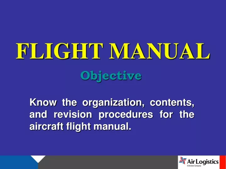
FLIGHT MANUAL. Objective. Know the organization, contents, and revision procedures for the aircraft flight manual. Sections 1 through 4 contain the FAA approved data necessary to operate the basic helicopter in a safe and efficient manner.

E N D
FLIGHT MANUAL Objective Know the organization, contents, and revision procedures for the aircraft flight manual.
Sections 1 through 4 contain the FAA approved data necessary to operate the basic helicopter in a safe and efficient manner. Appendix A contains the approved supplements for optional equipment, which shall be used in conjunction with the basic Flight Manual when the respective optional equipment kits are installed.
INTRODUCTION • ORGANIZATION • This Rotorcraft Flight Manual is divided into four sections with an appendix as follows: • Section 1 - LIMITATIONS • Section 2 - NORMAL PROCEDURES • Section 3 - EMERGENCY AND MALFUNCTION PROCEDURES • Section 4 - PERFORMANCE • Appendix - OPTIONAL EQUIPMENT AND SUPPLEMENTS
The Manufacturer's Data (BHT-206L3-MD-l) manual, contains information to be used in conjunction with the Flight Manual. The manual is divided into four sections: • Section 1 - WEIGHT AND BALANCE • Section 2 - SYSTEMS DESCRIPTION • Section 3 - OPERATIONAL INFORMATION • Section 4 - HANDLING AND SERVICING MAINTENANCE
TERMINOLOGY WARNINGS, CAUTIONS, AND NOTES Warnings, cautions, and notes are used throughout this manual to emphasize important and critical instructions as follows: WARNING AN OPERATING PROCEDURE, PRACTICE, ETC., WHICH, IF NOT CORRECTLY FOLLOWED, COULD RESULT IN PERSONAL INJURY OR LOSS OF LIFE.
CAUTION AN OPERATING PROCEDURE, PRACTICE, ETC., WHICH IF NOT STRICTLY OB-SERVED, COULD RESULT IN DAMAGE TO OR DESTRUCTION OF EQUIPMENT. NOTE An operating procedure, condition, etc., which is essential to highlight.
USE OF PROCEDURAL WORDS The concept of procedural word usage and intended meaning which has been adhered to in preparing this manual is as follows: “Shall" has been used only when application of a procedure is mandatory. "Should” has been used only when application of a procedure is recommended. “May" and "need not" have been used only when application of a procedure is optional. “Will" has been used only to indicate futurity, never to indicate a mandatory procedure.
SECTION 1 - LIMITATIONS GENERAL Compliance with the limitations section is required by appropriate operating rules. Anytime an operating limitation is exceeded, an appropriate entry shall be made in the helicopter logbook. The entry shall state which limit was exceeded, the duration of time, the extreme value attained, and any additional information essential in determining the maintenance action required. Intentional use of transient limits is prohibited.
BASIS OF CERTIFICATION This helicopter is certified under Civil Air Regulation, Part 6, Rotorcraft Airworthiness, Normal Category. TYPE OF OPERATION The basic configured helicopter is approved for seven-place seating and is certified for land operation under day or night VFR nonicing conditions. Flight operations are approved with the landing gear crosstube fairings installed or removed.
NOTE All unsecured items shall be removed from cabin when any door is removed. Flight with any combination of doors off is approved. Refer to AIRSPEED limitations. OPTIONAL EQUIPMENT The following equipment shall be installed when conducting flight operations in falling and/or blowing snow to reduce possibility of engine flameout:
The Snow Deflector Kit or the Particle Separator Engine Air Induction System Kit and the Snow Deflector Kit. (See BHT-206L3-FMS-3 and BHT206L3-FMS-7.) Refer to appropriate Flight Manual Supplement(s) for additional limitations, procedures, and performance data. FLIGHT CREW The minimum flight crew consists of one pilot who shall operate the helicopter from the right crew seat. The left crew seat may be used for an additional pilot when the approved dual controls are installed.
WEIGHT AND CENTER OF GRAVITY WEIGHT CAUTION LOADS THAT RESULT IN GROSS WEIGHTS ABOVE 4,150 POUNDS SHALL BE CARRIED ON THE CARGO HOOK AND SHALL NOT BE IMPOSED ON LANDING GEAR. Maximum approved gross weight for takeoff and landing is 4,150 pounds. Minimum combined crew weight at fuselage station 65.0 is 170 pounds.
CENTER OF GRAVITY LONGITUDINAL NOTE Ballast as required to maintain weight empty CG within limits shown on Center of Gravity vs Weight Empty chart in Maintenance Manual. Longitudinal center of gravity limits are variable depending on gross weight. The forward CG limit varies between stations 118.0 and 119.2. The aft CG limit varies between stations 126.7 and 128.5. NOTE Station 0 (reference datum) is located 55.16 inches forward of forward jack point centerline.
CENTER OF GRAVITY LATERAL Lateral center of gravity limits are 4.0 inches left of and 3.5 inches right of fuselage centerline. DOOR(S) OFF Actual weight change shall be determined after doors have been removed and ballast readjusted, if necessary, to return empty weight center of gravity within allowable limits.
AIRSPEED Basic VNE is 130 KIAS (150 MPH) sea level to 3,000 feet density altitude. Decrease VNE for ambient conditions in accordance with AIRSPEED LIMITATIONS placard. Refer to Placards and Decals. VNE is 84 KIAS (96 MPH) at 85 to 100% TORQUE takeoff power. VNE is 90 KIAS (104 MPH) with any door(s) off, not to exceed placarded VNE.
ALTITUDE Maximum operating pressure altitude is 20,000 feet. NOTE For high altitude pressure operation, refer to appropriate rules for oxygen requirements. AMBIENT AIR TEMPERATURE The maximum sea level ambient air temperature for operation is +51.7oC (+125oF) and decreases with pressure altitude at the standard lapse rate of 2oC (3.6oF) / 1000 feet to 20,000 feet. MANEUVERING Aerobatic maneuvers are prohibited.
GENERATOR DC LOAD • Continuous operation: 0 to 90% • Maximum: 90% • POWERPLANT • Allison model 250-C30P • GAS PRODUCER RPM • Continuous operation: 63 to 105% • Maximum: 105% • Maximum transient: 106% • (Do not exceed 10 seconds above 105%)
POWER TURBINE RPM • WARNING • USE OF THE THROTTLE TO CONTROL RPM IS NOT AUTHORIZED. (Refer to Section 3, for exception) • Minimum: 97% • Continuous operation: 97 to 100% • Maximum continuous: 100% • Transient overspeed range: 100 to 103% • NOTE • Refer to Allison Operation and Maintenance Manual for transient overspeed limits.
TURBINE OUTLET TEMPERATURE (TOT) • WARNING • EXCEEDING 768oC TURB OUT TEMP OR 100% TORQUE CAN CAUSE GAS PRODUCER TOPPING WITH RESULTANT ROTOR RPM DROOP. • Continuous operation: 100 to 716oC • Maximum continuous: 716oC • 5 minute takeoff range: 716 to 768oC • Maximum for takeoff: 768oC • Maximum transient (10 seconds): 768 to 871oC • Maximum for starting and shutdown 927oC • (Do not exceed 10 seconds above 768oC)
NOTE • Intentional use of power transient area (768 to 871oC) is prohibited. The TURB OUT TEMP gage is equipped with a red warning light that will illuminate when either of the following conditions occur: 770 to 927oC more than 10 seconds or above 927oC. • ENGINE TORQUE • Continuous operation: 0 to 85% • Maximum continuous: 85% • 5 minute takeoff range 85 to 100% • Maximum for takeoff: 100% • Maximum transient (5 seconds): 105%
FUEL PRESSURE • Minimum 4 PSI • Continuous operation: 4 to 25 PSI • Maximum: 25 PSI • Minimum for use of type A, A-l, or JP-5 • fuel, or any mixture of these, at ambient 8 PSI temperature below -18oC (0oF) • ENGINE OIL PRESSURE • Minimum for idle: 50 PSI • Operations below 79% N1: 50 to 90 PSI • Cont. operation below 94% N1: 90 to 115 PSI • Continuous operation: 115 to 130 PSI • Maximum: 130 PSI
ENGINE OIL TEMPERATURE • Continuous operation: 0 to 107oC • Maximum: 107oC • ANTI-ICE • The maximum ambient temperature for use of engine anti-ice is 4.4oC (40oF). • ENGINE ANTl-lCING shall be ON for flight in visible moisture in temperature below 4.4oC (40oF).
STARTER Limit starter energize time to the following: Ext. Power Start Battery Start 40 Seconds ON 60 Seconds ON 30 Seconds OFF 60 Seconds OFF 40 Seconds ON 60 Seconds ON 30 Seconds OFF 60 Seconds OFF 40 Seconds ON 60 Seconds ON 30 Minutes OFF 30 Minutes OFF
TRANSMISSION TRANSMISSION OIL PRESSURE Minimum: 30 PSI Continuous operation: 40 to 70 PSI Maximum: 70 PSI TRANSMISSION OIL TEMPERATURE Continuous operation: 15 to 110oC Maximum: 110oC
ROTOR ROTOR RPM - POWER ON Minimum transient (5 seconds): 95% Minimum: 97% Continuous operation: 97 to 100% Maximum continuous: 100% Maximum transient (5 minutes): 103% ROTOR RPM - POWER OFF Minimum: 90% Maximum: 107%
FUEL AND OIL Turbine fuel ASTM-D-1655, Type B, or MIL-T-5624, Grade JP-4, may be used at all ambient temperatures. Turbine fuel ASTM-D-1655, Type A or A-l, or MIL-T-5624, Grade JP-5, limited to ambient temperatures above -17.8oC (0oF) when equipped with fuel pressure gage PIN 206-075-676-101, -105, or -111. Turbine fuel ASTM-D-1655, Type A or A-l, or MIL-T-5624, Grade JP-5, limited to ambient temperatures -32oC (-25oF) and above when equipped with fuel pressure gage PIN 206-075-676-117, red triangle at 8PSI.
NOTE Anti-icing fuel additives are not required for any ambient temperature. Refer to Allison Operation and Maintenance Manual for cold weather fuel and blending instructions. ENGINE OIL Turbine oil MIL-L-7808 may be used at all ambient temperatures. DOD-L-85734 (AS) or MIL-L-23699 limited to ambient temperatures above -40oC / F). NOTE Refer to Allison Operation and Maintenance Manual and BHT206L3-MD-l manual for approved oils and mixing of oils of different brands, types, and manufacturers.
TRANSMISSION AND TAIL ROTOR GEARBOX OIL Turbine oil MIL-L-7808 may be used at all ambient temperatures. DOD-L-85734(AS) or MIL-L-23699 limited to ambient temperatures above -40oC / F). HYDRAULIC Hydraulic fluid MIL-H-5606 may be used at all ambient temperatures.
SECTION 2 - NORMAL PROCEDURES INTRODUCTION This section contains instructions and procedures for operating the helicopter from the planning stage, through actual flight conditions, to securing the helicopter after landing. Normal and standard conditions are assumed in these procedures. Pertinent data in other sections is referenced when applicable. The instructions and procedures contained herein are written for the purpose of standardization and are not applicable to all situations.
OPERATING LIMITATIONS The minimum and maximum limits, and the normal and cautionary operating ranges for the helicopter, and its subsystems, are indicated by instrument markings and placards. The instrument markings and placards represent careful aerodynamic calculations that are substantiated by flight test data. Refer to Section 1, for a detailed explanation of each operating limitation.
FLIGHT PLANNING Each flight should be planned adequately to ensure safe operations and to provide the pilot with the data to be used during flight. Check type of mission to be performed and destination. Select appropriate performance charts to be used from Section 4, and/or the appropriate optional equipment supplement. TAKEOFF AND LANDING DATA Refer to Section 1 for takeoff and landing weight limits, and to Section 4 for performance information.
WEIGHT AND BALANCE • Determine proper weight and balance of the helicopter as follows: • 1. Consult BHT-206L3-MD-l for instructions. • 2. Compute takeoff and anticipated landing gross weight, check helicopter Center of Gravity (CG) locations, and determine weight of fuel, oil, payload, etc. • 3. Ensure Weight / CG limits listed in Section 1 have not been exceeded.
PREFLIGHT SEQUENCE
SECTION 3 EMERGENCY / MALFUNCTION PROCEDURES INTRODUCTION The following procedures contain the indications of failures or malfunctions which affect safety of the crew, the helicopter, ground personnel or property; the use of emergency features of primary and backup systems; and appropriate warnings, cautions, and explanatory notes. The following list fault conditions and corrective actions for warning lights and caution lights respectively.
DEFINITIONS The following terms indicate the degree of urgency in landing the helicopter. LAND AS SOON AS POSSIBLE: Land without delay at the nearest suitable area (i.e., open field) at which a safe approach and landing is reasonably assured. LAND AS SOON AS PRACTICAL: The landing site and duration of flight are at the discretion of the pilot. Extended flight beyond the nearest approved landing area is not recommended.
The following terms are used to describe the operating condition of a system, subsystem, assembly, or component. Affected: Fails to operate in the intended or usual manner. Normal: Operates in the intended or usual manner. All procedures listed herein assume the pilot gives first priority to helicopter control and a safe flight path.
WARNING LIGHTS PANEL WORDING FAULT CONDITION CORRECTIVE ACTION ENG OUT (audio if functional) Gas Producer less than 55 + 3% RPM; Power Turbine RPM decreasing Verify engine condition. Accomplish engine failure procedures. Turn BAT switch OFF and Land as soon as practical. If BATTERY RLY caution light illuminates, land as soon aspossible BATTERY HOT Battery overheating. Temperature 140oF (60oC) or higher. LITTER DOOR OPEN Litter door not securely latched. Close door securely before flight. If light illuminates during flight, land as soon as practical.
CAUTION LIGHTS PANEL WORDING FAULT CONDITION CORRECTIVE ACTION ROTOR LOW RPM (Audio & Light) ROTOR below 90% RPM Reduce collective pitch and ensure throttle is fully open. Light and audio should cease when ROTOR increases above approximately 90% RPM. TRANS OIL PRESS XMSN OIL pressure is below minimum. Reduce power; verify fault with gauge. Land as soon as possible. TRANS OIL TEMP XMSN OIL temperature is at or above red line. Reduce power; verify fault with gage. Land as soon as possible.
PANEL WORDING FAULT CONDITION CORRECTIVE ACTION BATTERY RLY Battery relay has malfunctioned to closed position with BAT switch OFF. If BATTERY HOT light is illuminated, land as soon as possible. Battery will not drop off line. FUEL LOW Approximately 50 - 75 LBS of fuel remain. Verify FUEL QTY. Land as soon as practical. Land as soon as possible. ENGCHIP Metallic particles in engine oil. Land as soon as possible. TRANS CHIP Metallic particles in transmission oil.
PANEL WORDING FAULT CONDITION CORRECTIVE ACTION Land as soon as possible. Clean before next flight. FUEL FILTER AIR FRAME fuel filter clogged. T/R CHIP Metallic particles in tail rotor gearbox oil. Land as soon as possible. GEN switch - RESET then ON. If GEN FAIL light remains illuminated, GEN switch - OFF. Land as soon as practical. GEN FAIL Failure of generator.
PANEL WORDING FAULT CONDITION CORRECTIVE ACTION Descend below 6,000 feet pressure altitude, if flight permits. Land as soon as practical. R/FUEL PUMP Right pump of the dual boost pump assembly failed. WARNING IF BOTH FUEL BOOST PUMPS FAIL, UNUSABLE FUEL MAY BE AS HIGH AS 160 POUNDS DUE TO INABILITY TO TRANSFER FUEL FROM FORWARD CELLS. LAND AS SOON AS PRACTICAL. Descend below 6,000 feet pressure altitude, if flight permits. Land as soon as practical. L/FUEL PUMP Left pump of the dual boost pump assembly failed.
ENGINE EMERGENCIES • ENGINE FIRE DURING START OR SHUTDOWN • INDICATIONS: • 1. Excessive TURBINE OUTLET TEMP (TOT). • 2. Visible smoke or fire. • PROCEDURE: • 1. Throttle - Closed. • 2. FUEL VALVE switch - OFF. • 3. STARTER switch - Press to motor engine until TOT stabilizes at normal temperature. • 4. Shut down and exit helicopter.
ENGINE FIRE DURING FLIGHT • INDICATIONS: • 1. Smoke. • 2. Fumes. • 3. Fire. • PROCEDURE: • 1. Throttle - Closed. • 2. Autorotation - Enter Immediately. • 3 FUEL VALVE switch - OFF. • 4. BAT switch - OFF. • 5 GEN switch - OFF. • 6. Execute autorotative descent and landing. • Do not restart engine until corrective • maintenance has been performed.
ENGINE FAILURE • HOVERING IN GROUND EFFECT • INDICATIONS: • 1. Left yaw. • 2. ENG OUT warning light illuminated. • 3. Engine out audio (if functional) activated when GAS PRODUCER drops below 55% RPM. • 4. ROTOR RPM decreases with ROTOR LOW caution light and audio on when ROTOR drops below 90% RPM. • 5. Engine instruments indicate power loss.
PROCEDURE: • 1. Maintain heading and landing attitude. • 2. Adjust Collective to control rate of descent and cushion landing. It is recommended that level touchdown be made prior to passing through 70% Rotor RPM. • 3 Land. • 4. Shut down helicopter.
ENGINE FAILURE • HOVERING OUT OF GROUND EFFECT • INDICATIONS: • 1. Left yaw. • 2. ENG OUT warning light illuminated. • 3. Engine out audio (if functional) activated when GAS PRODUCER drops below 55% RPM. • 4. ROTOR RPM decreases with ROTOR LOW caution light and audio on when ROTOR drops below 90% RPM. • 5. Engine instruments indicate power loss.
PROCEDURE: • 1. Maintain heading and attitude control. • 2. Collective Adjust as required to maintain 90 to 107% ROTOR RPM. • 3. Apply collective pitch as flare effect decreases to further reduce forward speed and cushion landing. It is recommended that level touch down be made prior to passing through 70% ROTOR RPM. Upon ground contact, collective pitch shall be reduced smoothly while maintain-ing cyclic in neutral or centered position.
CAUTION EXCESSIVE GROUND RUN WITH COLLECTIVE UP, OR ANY TENDENCY TO FLOAT FOR LONG DISTANCE PRIOR TO GROUND CONTACT SHOULD BE AVOIDED. NOTE ROTOR RPM maintained at the high end of the operating range will provide maximum rotor energy to accomplish the landing, but will cause an increased rate of descent.