Download
1 / 37
370 likes | 722 Views
Chapter 10 Sheet Metal Design . Chapter 10 - Objectives. After completing this chapter, you will be able to perform the following: Start the Autodesk Inventor sheet metal environment Modify settings for sheet metal design Create sheet metal parts

E N D
Chapter 10 - Objectives • After completing this chapter, you will be able to perform the following: • Start the Autodesk Inventor sheet metal environment • Modify settings for sheet metal design • Create sheet metal parts • Modify sheet metal parts to match design requirements • Create sheet metal flat patterns • Create drawing views of sheet metal parts
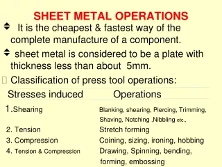
Sheet Metal Fabrication • Sheet Metal Uses • Enclosures • Brackets • Structures or Frames
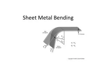
Sheet Metal Fabrication • Bend Tables • L=A+B-x Construction • L Unfolded Length • A Length of folded face 1 • B Length of folded face 2 • x Adjustment from bend table • Measurements A and B are to the intersection of the extended outer faces on either side of the bend. This intersection is used when the angle of the bend is less than or equal to 90 degrees.
Sheet Metal Fabrication • Bend Tables • L=A+B-x Construction • L Unfolded Length • A Length of folded face 1 • B Length of folded face 2 • x Adjustment from bend table • Use these measurements when the bend angle is greater than 90 degrees. The measurements are parallel to the face, and tangent to the outer surface of the bend. The same formula is used to determine the unfolded length of the part.
Sheet Metal Parts • Sheet Metal Design Methods • Folded State • Flat State • Disjointed Solids • Shelled Parts
Sheet Metal Parts • Sheet Metal Part Template(s) • Sheet Metal Environment
Sheet Metal Tools • Sheet Metal Rules • Click the Style and Standard Editor from the Format menu • Sheet metal specific parameters driven by rules
Sheet Metal Tools • Sheet Metal Styles • Bend Tab
Sheet Metal Tools • Sheet Metal Styles • Bend Transitions • Controls the intersection of edges across a bend in the flattened sheet.
Sheet Metal Tools • Sheet Metal Styles • Corner Tab • Relief Shape • Jacobi Corner
Sheet Metal Tools • Sheet Metal Unfold Method • Linear – KFactor Value • Bend Table
Sheet Metal Tools • Sheet Metal Defaults • After you define sheet metal rules • Use the Sheet Metal Defaults tool to select the rule that is active for the sheet metal part
Sheet Metal Tools • Sheet Metal Face • Extrudes a closed profile a distance equal to the sheet metal thickness • Unfold Options • Relief Options
Sheet Metal Tools • Contour Flange • Created from an open sketch profile • Bends are added at sharp intersections
Sheet Metal Tools • Flange • Creates a sheet metal face and bend to an existing face • Extends the full length of the selected edge • Corner Edits – click glyph in corner
Exercise 10-1 • Creating Sheet Metal Parts
Sheet Metal Tools • Hem • Eliminate sharp edges • Strengthen an open edge of a face • Material is folded back over a face with a small gap
Exercise 10-2 • Hems
Sheet Metal Tools • Fold • Turns a flat pattern into a folded model • Add folds at sketched lines
Sheet Metal Tools • Bend • Child objects of other features • When two faced connect • Connect disjointed face
Exercise 10-3 • Modifying Sheet Metal Parts
Sheet Metal Tools • Cut • Sheet Metal implementation of Extrude > Cut • Distance of the cut is equal to the Thickness parameter • Project Flat Pattern • Cut Across Bend • Define Distance
Exercise 10-4 • Cut Across Bend
Sheet Metal Tools • Corner Seam • Created when three faces meet • Create mitered gaps between coplanar faces
Sheet Metal Tools • Corner Round • Sheet Metal specific Fillet tool • Corner Chamfer – Sheet Metal specific Chamfer tool
Sheet Metal Tools • Create Punch • iFeature • Center Point • Parameters • Punch ID • Custom Depth • Simplified Sketch
Sheet Metal Tools • PunchTool • Center Point required • Creates Cuts and 3D Deformations • Dimples • Louvers • Punch Folder • Applications Options > iFeature tab • Flat Pattern • Representation
Exercise 10-5 • Punch Tool
Sheet Metal Tools • Flat Pattern • Represents the starting point for sheet metal part manufacturing • Creates a 3D model of the unfolded part • Displayed in a 2D drawing view • Flat Pattern – Browser • Flat Pattern – Extents, area
Sheet Metal Tools • Flat Pattern • Extents, area • Edit Definition • Punch Representation • Flat Patten Features • Effect Flat Pattern Only
Sheet Metal Tools • Common Tools -Similar to the part Features Panel Bar • Work Features • Holes • Catalog Tools • Feature Patterns • Mirror • Copy Object • Derived Component • Parameters • Create iMate
Detailing Sheet Metal Designs • Detailing Sheet Metal Designs • 3D Model and Flat Patterns
Exercise 10-6 • Documenting Sheet Metal Designs
Applying Your Skills • Skill Exercise 10-1
Project Exercise – Chapter 10Sheet Metal Design • In Appendix A
Checking Your Skills • The base feature of a sheet metal part is most often a: • Revolve • Face • Extrude • Flange • What is the correct procedure to change the edges connected by a bend feature? • Suppress the existing bend, and add a new bend. • Delete the existing bend, and add a new bend. • Edit the bend, and select the new edges. • Create a corner seam between the desired faces. • Which tool would you use to create a full-length rectangular face off of an existing face edge? • Flange • Extrude • Face • Bend • What action is required to update a flat pattern model? • Right-click on the flat pattern in the browser, and select Update. • Erase the existing flat pattern, and recreate it. • Create a new flat pattern drawing view. • The flat pattern is updated automatically. • Sheet metal parts can contain features created with Autodesk Inventor modeling tools. • Sheet Metal Style settings cannot be overridden; a new style must be created for different settings. • During the creation of a sheet metal face, the face can extend to meet another face and connect to it with a bend. • A sheet metal cut that used the Distance extents option must be created equal to the Thickness parameter. • What is a common term for a three-bend intersection? • When creating a sheet metal punch, you can select an alternate 2D representation to display in flat patterns and drawing views.