Download
1 / 25
250 likes | 495 Views
Redundancy. ATM Switch. Objectives. Define the term redundancy as it applies to the service provider network environment Explain the difference between hardware and software redundancy List the redundant components of the Marconi ASX-4000 series switches

E N D
Redundancy ATM Switch
Objectives • Define the term redundancy as it applies to the service provider network environment • Explain the difference between hardware and software redundancy • List the redundant components of the Marconi ASX-4000 series switches • Define the function of APS in a network environment • State the functionality of redundant SCPs, TCMs, power supplies and fan trays within the ASX-4000 series switches • Discuss how connection preservation, call preservation and call resiliency supports redundancy in a network environment • Configure APS Redundancy and dual SCPs • Validate the need to incorporate sparing into the process of network design and maintenance
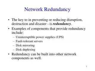
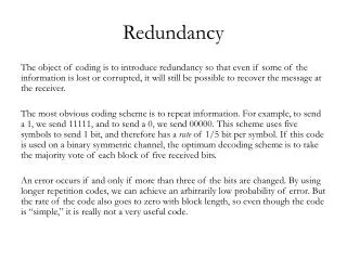
Redundancy • Redundancy defined: • (1) more than is actually needed for proper operation • (2) items of equipment which are provided in duplicate (or in some cases triplicate) so that a required grade of service may be reliably achieved • Contributes to system level availability which improves overall network resiliency • Hardware redundancy provides failover support to primary resources by allowing for the installation of two identical hardware components in a network unit
ASX-4000 Series: Redundant Hardware Components • Switch Control Processor (SCP) • Timing Control Module (TCM) • Power Supply • Fan Tray • With SONET APS/SDH MSP: • Fabrics • Port Card • Port
Terms: Working Protection Active Standby Features: Linear: point-to-point 1+1 Protection Unidirectional or bi-directional Non-revertive or revertive + ASX-4000 Series: APS (Automatic Protection Switching) 1A1 2A1 ASX-4000 otherSONET Active Working Rx Working Tx Active Active Working Tx Working Rx Active Standby Protection Rx Protection Tx Standby Standby Protection Tx Protection Rx Standby Active Standby Standby Active R1A1
Port Series 1, Passive Series 2, Active and Passive Non-revertive and Revertive Port Card Series 1, Passive Series 2, Active and Passive Non-revertive Fabric Active and Passive Non-revertive and Revertive Example: 10G Redundant (1&2) 20G Non-Redundant (3&4) 5 Gbps Fabric 3 5 Gbps 5 Gbps Fabric 4 5 Gbps ASX-4000 Series: Redundancy + 40 Gbps Backplane Fabric 1 Card 1AB 10 Gbps Card 1CD Fabric 2 Card 2AB 10 Gbps Card 2CD Card 3AB 10 Gbps Card 3CD 10 Gbps Card 4AB Card 4CD
2 4 1 4 1 3 2 3 C D A B C D A B A B C D A B C D + ASX-4000 Series: Fabrics and Port Cards SCP X SCP Y Logical Netmod Logical Netmod Fabric 2 Fabric 1 Port Card 2 Port Card 2 Port Card 1 Port Card 1 Port Card 4 Port Card 4 Port Card 3 Port Card 3 Fabric 4 Fabric 3 A C A C A C A C Logical Netmod Logical Netmod B D B D B D B D Slots 1 2 3 4 5 6 7 8 9 10 11 12 13 14
ASX-4000 Series: APS Redundancy Fabric ATM SWITCH:redundancy-> ? fabric> The fabric directory group> The group directory netmod> The netmod directory port> The port directory portcard> The portcard directory ATM SWITCH:redundancy-> fabric ? commit Commit changes made via protect and unprotect commands protect Protect the specified Non Redundant fabric show Display Fabric Redundancy Information switchover Switch specified Fabric to active | standby unprotect Unprotect the specified Redundant fabric
ASX-4000 Series: APS Redundancy Fabric (cont) ATM SWITCH:redundancy-> fabric protect ? [-fabric] <integer> Fabric Index ATM SWITCH:redundancy-> fabric protect 1 WARNING: The command will not take effect until it is enabled using the commit command. ATM SWITCH:redundancy-> fabric commit WARNING: This command will delete the configuration values corresponding to the protection fabric(s) and all the netmods connected to the protection fabric. This command will also reboot the switch. Do you wish to continue (y or n): y ATM SWITCH:redundancy-> fabric show Fabric Admin Mode Oper State Redundancy State Pending Mode Committed 1 working active armed none yes 2 protection standby armed none yes 3 unprotected unprotected unprotected none yes 4 unprotected unprotected unprotected none yes
ASX-4000 Series: APS Redundancy Netmod and Port Card ATM SWITCH:redundancy-> netmod ? modify Modify Netmod Redundancy Configuration show Display the Netmod Redundancy State Information switchover Switch specified Netmod to active | standby ATM SWITCH:redundancy-> netmod show Netmod Admin Mode Oper State Cloning State Redundancy State 1A working N/A done armed 1B protection N/A done armed 1C protection active done armed 1D working standby done armed 3A protection active done armed 3B protection active done armed 3C unprotected N/A N/A unprotected 3D unprotected N/A N/A unprotected ATM SWITCH:redundancy-> portcard ? show Display Portcard Redundancy Information : ATM SWITCH:redundancy-> portcard show PortCard Cloning State 1AB done 1CD done 2AB in_progress 2CD in_progress 3AB NA 3CD NA
ASX-4000 Series: APS Configuration ATM SWITCH:redundancy:-> port ? apsgroup> The aps group directory show Displays APS Port Table Information ATM SWITCH:redundancy-> port show PortName Admin Mode Oper Mode GroupName 1A1 working active aps1A1 1A2 working active aps1A2 1A3 working active aps1A3 1A4 working active aps1A4 : 2B1 protection standby aps1B1 2B2 protection standby aps1B2 2B3 protection standby aps1B3 2B4 protection standby aps1B4 : 3A1 unprotected unprotected 3A2 unprotected unprotected 3A3 unprotected unprotected 3A4 unprotected unprotected : 4A1 unprotected unprotected 4A2 unprotected unprotected 4A3 unprotected unprotected 4A4 unprotected unprotected
ASX-4000 Series: APS Configuration (cont) ATM SWITCH:redundancy-> port apsgroup show Group Aps Command Line State Aps Mode Revert Name Working Protection Oper Config Mode Timer APS1A1 no_request sf sf uni uni off 5 APS1A2 no_request none none uni uni off 5 APS1A3 no_request sf sf uni uni off 5 APS1A4 no_request sf sf uni uni off 5 APS1B1 no_request sf sf uni uni off 5 APS1B2 no_request sf sf uni uni off 5 APS1B3 no_request sf sf uni uni off 5 APS1B4 no_request sf sf uni uni off 5 ATM SWITCH:redundancy-> port apsgroup modify Usage: [-name] <text> Group Name [[-revert_mode] (on|off)] Revertive Mode [[-revert_timer] (1..60)] Revertive Timer [[-command] <aps_command_inp>] Command [[-config_mode] (uni | bi) APS configuration mode
How APS Affects Configuration ATM SWITCH:-> connections channel ATM SWITCH: connections channel-> new 3b3 0 150 r1a1 0 150 ATM SWITCH: connections channel-> new r1a1 0 150 3b3 0 150 ATM SWITCH: connections channel-> show 3b3 0 150 Input Output AtmIf VPI VCI AtmIf VPI VCI ServCat Protocol Name 3B3 0 150 R1A1 0 150 UBR pvc my4000:interfaces atmif-> show 1a1 There are no entries matching your query. ATM SWITCH:interfaces atmif-> show r1a1 AtmIf Admin ATM-Rate CDVT AIS/RDI Auto BW Mgmt R1A1 up 599.0M 250 disabled N/A
Revertive/Non-revertive Mode ATM SWITCH:redundancy-> group ATM SWITCH:redundancy group-> ? modify Modify Redundancy Group Attributes show Display Redundancy Group Information ATM SWITCH:redundancy group-> show Group Revert Mode Qualification Timer Error Threshold Error Block Size r12 off 5 2 10 r34 off 5 2 10 ATM SWITCH:redundancy group-> modify r12 on ATM SWITCH:redundancy group-> show Group Revert Mode Qualification Timer Error Threshold Error Block Size r12 on 5 2 10 r34 off 5 2 10
ASX-4000 Series: Switch Control Processors (SCPs) • Failover support provided when two SCPs are installed in the ASX-4000 series switches • When using dual SCPs, identical SCPs must be installed • In dual mode, controlling SCP emits a heartbeat at regular intervals which is monitored by the standby SCP • In the event of an SCP failure, the heartbeat disappears and standby SCP takes control of the switch • Hot-swappable • SCP in slot X is the primary SCP by default Dual SCPs
Dual SCP Configuration ATM SWITCH:hardware dualscp-> ? modify Modify parameters of the dualscp configuration show Show dualscp information switchover Enable Dualscp Switchover synchronize Synchronize with dual scp ATM SWITCH:hardware dualscp-> show Threshold Auto CDB Sync Sync SCP State Primary Failover (in secs) Remove SyncMode Requests Failures --------------------------------------------------------------------------- 1X other X enabled 2 disabled automatic 3 0 Synchronization queue : CDB Synchronization state : Idle SVx/SPVx state transfer %: N/A SVx/SPVx dropped calls : N/A SVx/SPVx transfer status : N/A Last switchover time : N/A Standby Software Version: S_ForeThought_ATM_9.0.0.N GA-Update (1.157933) ATM SWITCH:hardware dualscp-> modify ? [[-primary] (X|Y)] Primary SCP [[-failover] (enabled|disabled)] Auto Failover [[-threshold] <integer>] Failover Threshold (sec) [[-autoremove] (enabled|disabled)] Auto Remove Old Files [[-cdbsyncmode] (manual|automatic)] CDB Sync Mode [[-resetstandby] (enabled|disabled)] Reset Standby SCP
ASX-4000 Series: Timing Redundancy • Transformer Interface Module (TIM) • Physical connection area for external timing sources • Optional Timing Control Modules (TCMs) • Verifies the timing reference and distributes a high quality clock • Located on daughter card for each SCP • In a dual configuration, the TCMs must be of the same type (both DS1 or both E1) ASX-4000/M BITSTiming Source TIM TCM Rest of ASX-4000/M SCE SCP-IM SCP
ASX-4000 Series: Power Supplies • Load sharing • Each power supply on both the 4000 and 4000M is equipped with two internal fans that help cool the power supplies • Available in AC or DC Configurations: • ASX-4000: • 4 AC modules (the fourth AC module provides redundancy) • 5 DC modules (the fifth DC module provides redundancy) • ASX-4000M: • 4 DC modules (the fourth DC module provides redundancy) • In the event of a single power supply module failure: • LED(s) on front panel of switch for failed power supply module will light • Hot-swappable ASX-4000 AC Power Modules ASX-4000M DC Power Modules
ASX-4000 Series: Fan Trays • Two fan trays are contained in the ASX-4000 series switches • State of each fan monitored by SCP • Fan trays are hot-swappable Bottom fan tray of ASX-4000
PVC/PVP Connection Preservation • Maintains cell flow on PVCs and PVPs in the event of an SCP failure • When connection preservation has been enabled(by default), permanent connections in the connection table allow the fabric to continue forwarding cells without an active SCP • Connection preservation is enabled by default on 40 Gbps and 10 Gbps platforms (includes the ASX-4000 series, ASX-1000/1200 and TNX-1100) but not on 2.5 Gbps platforms (ASX-200BX/TNX-210) • While the SCP is inactive (failing over or rebooting), no new PVCs or PVPs can be created
SVx/SPVx Call Preservation • When SCP is switched over or fails over: • Cell flow on existing switched connections is maintained • Call connections not transferred to the backup SCP will not be preserved (calls established for less than five minutes) • Call Preservation is disabled by default on all Marconi ATM switches with dual SCP configuration • System Requirements: • Dual SCPs • P5 or greater SCPs
+ SPVx Redirection • Allows SPVPCs/SPVCCs to have two destinations associated with a call, thus creating resilient SPVxs • An initial SPVx call is set up to a primary destination (with call redirection enabled); if primary destination is inaccessible, the call is then automatically switched over to a secondary/backup destination • Protects against the following types of failures: • Transient errors • Destination switch going down • Link between ATM network and destination switch going down 31 Primary Destination WAN Source switch Secondary Destination
+ Source SPVx Resiliency • Enhances destination SPVx resiliency feature by providing resiliency on the source end of a connection • To create end-to-end resiliency, the same SPVx is created on the source and another switch at the local site • Protects against the following types of failures: • Primary data source going down • Link between primary data source and primary source switch going down • Primary source switch on local site going down • Link between primary source switch and the network going down • Connection between primary source switch and destination going down Local site 1 1 4 Switch A(Source) WAN Router Destination Switch B
Sparing • Notion of spare components on-site for unexpected failure(s) • Proactive planning • Prompt replacement • Considerations: • Research contract types negotiated between your organization and Marconi • Level of Support Contract • Timely Replacement • Return for Repair Contract • Geographic location/environment of network equipment and amount of equipment per site • Cost of sparing at 5, 10 or 15% of the total individual pieces of operational equipment • Mean Time Between Failure (MTBF) Rates • Use of Spares • Other operational issues (when failed equipment is replaced with operational equipment)
Summary • Defined the term redundancy as it applies to the service provider network environment • Explained the difference between hardware and software redundancy • Listed the redundant components of the Marconi ASX-4000 series switches • Defined the function of APS in a network environment • Stated the functionality of redundant SCPs, TCMs, power supplies and fan trays within the ASX-4000 series switches • Discussed how connection preservation, call preservation and call resiliency supports redundancy in a network environment • Configured APS Redundancy and dual SCPs • Validated the need to incorporate sparing into the process of network design and maintenance