Download
1 / 27
270 likes | 500 Views
CprE 458/558: Real-Time Systems. Controller Area Network: Overview (Updated by: Ki-sung Koo, CprE 458/558 TA). Intra-vehicular communication. A typical vehicle has a large number of electronic control systems The growth of automotive electronics is a result of:

E N D
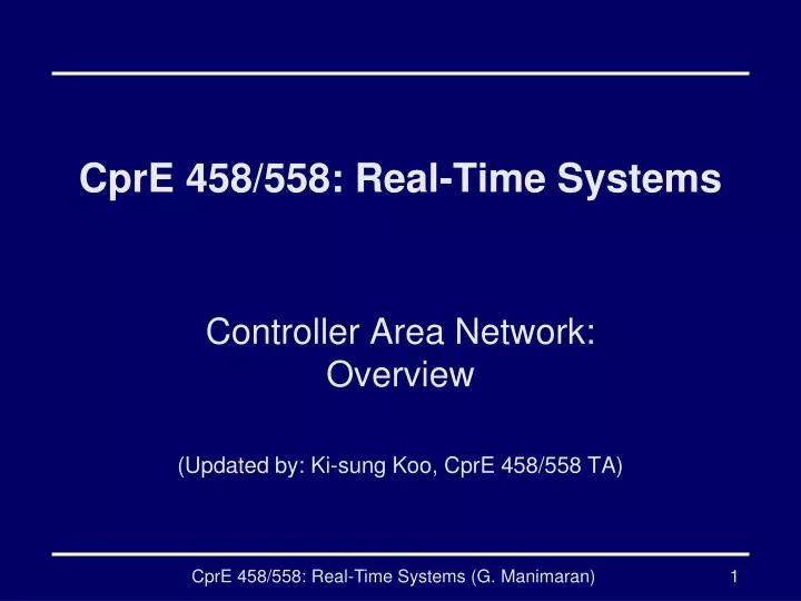
CprE 458/558: Real-Time Systems Controller Area Network: Overview (Updated by: Ki-sung Koo, CprE 458/558 TA) CprE 458/558: Real-Time Systems (G. Manimaran)
Intra-vehicular communication • A typical vehicle has a large number of electronic control systems • The growth of automotive electronics is a result of: • Customers wish for better comfort and better safety. • Government requirements for improved emission control • Reduced fuel consumption • Some of such control systems • Engine timing • Gearbox and carburetor throttle control • Anti-block systems (ABS) • Acceleration skid control (ASC) CprE 458/558: Real-Time Systems (G. Manimaran)
Intra-vehicular communication • An example of intra-vehicular communication. CprE 458/558: Real-Time Systems (G. Manimaran)
Intra-vehicular communication • The complexity of these functions implemented by these electronic control systems necessitates an efficient communication between them. • In addition, a number of systems are being developed which will cover more than one device. For example • ASC requires the interplay of the engine timing and carburetor control in order to reduce torque when drive wheel slippage occurs. • In the electronic gearbox control, the ease of gear changing can be improved by a brief adjustment to ignition timing CprE 458/558: Real-Time Systems (G. Manimaran)
How do we connect these control devices? • With conventional systems, data is exchanged by means of dedicated signal lines or wires. • But this is becoming increasingly difficult and expensive as control functions become ever more complex. • In the case of complex control systems in particular, the number of connections cannot be increased much further. • Solution: Use Fieldbus networksfor connecting the control devices CprE 458/558: Real-Time Systems (G. Manimaran)
Fieldbus Networks: basic motivation Why use Fieldbus Networks? To avoid this… Figure 1 Traditional Wiring - two pairs of cables can substitute all typical connections. CprE 458/558: Real-Time Systems (G. Manimaran)
Real-Time Communication Architecture Three different communication networks in real-time application. CprE 458/558: Real-Time Systems (G. Manimaran)
Intra-vehicular communication • A schematic diagram of a current in-vehicle network Smart Junction Box CprE 458/558: Real-Time Systems (G. Manimaran)
Fieldbus Networks • Fieldbuses are communication technologies and products used in vehicular, automation and process control industries. 1) Proprietary Fieldbuses (Closed Fileldbuses) • Proprietary Fieldbuses are an intellectual property of a particular company or body. 2) Open Fieldbuses • For a Fieldbus to be Open, it must satisfy the following criteria. a) The full Fieldbus Specification must be published and available at a reasonable price. b) Critical ASIC components must be available, also at a reasonable price. c) Well defined validation process, open to all of the Fieldbus users. CprE 458/558: Real-Time Systems (G. Manimaran)
Fieldbus Advantages 1) Reduces the complexity of the control system in terms of hardware outlay. 2) Resulting in the reduced complexity of the control system, project design engineering is made simpler, more efficient and conversely less expensive. 3) By selecting a recognized and well established system, this will make the Fieldbus equipment in you plant or plants interchangeable between suppliers. 4) The need to be concerned about connections, compatibility and other potential problems is eradicated. CprE 458/558: Real-Time Systems (G. Manimaran)
What constitutes a Fieldbus? The specification of a Fieldbus should ideally cover all of the seven layers of the OSI model. CprE 458/558: Real-Time Systems (G. Manimaran)
Fieldbus: OSI layer details • Physical Layer [1] What types of signals are present, levels, representation of 1's and 0's, what type of media connects, etc. • Link Layer [2] Techniques for establishing links between communicating parties. • Network Layer [3] Method of selecting the node of interest, method of routing data. • Transport Layer [4]Ensuring what was sent arrives at the receiver correcting any correctable problems. • Session Layer [5] Not applicable to Fieldbuses. • Presentation Layer [6] Not applicable to Fieldbuses. • Application Layer [7]Meaning of data. • The best way of covering layer 7 is to define standard profiles for standard devices. CprE 458/558: Real-Time Systems (G. Manimaran)
What Fieldbus Networks are currently on the market? • some of the Fieldbus technologies currently on the market • AS-Interface (Europe) • CAN (German, Bosch, we will discuss in detail) • Interbus (German, Phoenix Contract) • ModBus (America, Modicon) • Profibus (German, Siemens) • EtherNet (America, AB) • Controlnet (America, AB) • Etc. CprE 458/558: Real-Time Systems (G. Manimaran)
Controller Area Network (CAN) • Controller Area Network (CAN) is a fast serial bus that is designed to provide • an efficient, • Reliable and • very economical link between sensors and actuators. • CAN uses a twisted pair cable (dual-wire) to communicate at speeds up to 1Mbit/s (max) with up to 40 devices. • It originally developed to simplify the wiring in automobiles. • CAN (fieldbuse) are now used in machine and factory automation products as well. CprE 458/558: Real-Time Systems (G. Manimaran)
CAN features 1) Any node can access the bus when the bus is quiet. 2) Non-destructive bit-wise arbitration to allow 100% use of the bandwidth without loss of data (example) 3) Variable message priority based on 11-bit / 29 bit packet identifier 3) Peer-to-peer and multi-cast reception 4) Automatic error detection, signaling and retries 5) Data packets 8 bytes long 6) Asynchronous communication (Even Triggered) CprE 458/558: Real-Time Systems (G. Manimaran)
CAN architecture CAN Station 1 CAN Station 40 (max) CS1 CS2 CS3 CS40 …………. CAN Bus CprE 458/558: Real-Time Systems (G. Manimaran)
Working of the CAN network: example CprE 458/558: Real-Time Systems (G. Manimaran)
Tradeoff: CAN bus versus point-to-point connections • By introducing one single bus as the only means of communication as opposed to the point-to-point network, we traded off the channel access simplicity for the circuit simplicity • Since two devices might want to transmit simultaneously, we need to have a MAC protocol to handle the situation. • CAN manages MAC issues by using a unique identifier for each of the outgoing messages • Identifier of a message represents its priority. CprE 458/558: Real-Time Systems (G. Manimaran)
CAN: message format Supports only 11 bit identifier CprE 458/558: Real-Time Systems (G. Manimaran)
Extended CAN message format Supports 29 bit identifier CprE 458/558: Real-Time Systems (G. Manimaran)
Physical CAN connection *ECU (Electrical Control Unit) CprE 458/558: Real-Time Systems (G. Manimaran)
Implicit collision handling in the CAN bus • If two messages are simultaneously sent over the CAN bus, the bus takes the “logical AND” of all them • Hence, the messages identifiers with the lowest binary number gets the highest priority • Every device listens on the channel and backs off when it notices a mismatch between the bus’s bit and its identifier’s bit. CprE 458/558: Real-Time Systems (G. Manimaran)
Implicit collision handling in the CAN bus: example Node B notices a mismatch in bit # 3 on the bus. Therefore, it stops transmitting thereafter 1 1 1 BUS 0 0 0 0 0 0 1 1 1 Node A’s message-ID 0 0 0 0 0 0 1 1 1 1 Node B’s message-ID 0 0 0 0 0 Unlike the MAC protocols we learnt, in CAN a collision does not result in wastage of bandwidth. Hence, CAN achieves 100% bandwidth utilization CprE 458/558: Real-Time Systems (G. Manimaran)
Other applications of CAN 1) Concrete State Monitor & Control Ssytem CprE 458/558: Real-Time Systems (G. Manimaran)
Other applications of CAN 2 ) MRI Cooling System CprE 458/558: Real-Time Systems (G. Manimaran)
Other applications of CAN 3) Tram Energy Recycle System CprE 458/558: Real-Time Systems (G. Manimaran)
References • http://www.fieldbus.com.au/techinfo.htm#Top • http://www.esd-electronics.com/german/PDF-file/CAN/Englisch/intro-e.pdf • http://www.eng.man.ac.uk/mech/merg/FieldbusTeam/Fieldbus%20Introduction.htm#_Toc487265349 • “In-Vehicle Network Architecture for the Next-Generation Vehicles” Syed Masud Mahmud, Sheran Alles • http://www.can-cia.de/ • http://www.icpdas.com/products/Remote_IO/can_bus/application.htm CprE 458/558: Real-Time Systems (G. Manimaran)