Download
1 / 28
470 likes | 1.03k Views
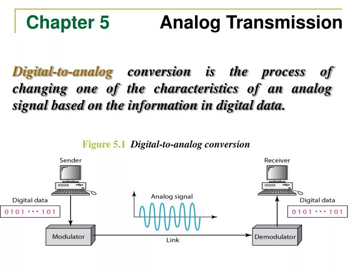
Chapter 5 Analog Transmission. Digital-to-analog conversion is the process of changing one of the characteristics of an analog signal based on the information in digital data. Figure 5.1 Digital-to-analog conversion. Chapter 4 Digital Transmission.

E N D
Chapter 5 Analog Transmission Digital-to-analog conversion is the process of changing one of the characteristics of an analog signal based on the information in digital data. Figure 5.1 Digital-to-analog conversion
Chapter 4 Digital Transmission • Data Encodingrefers the various techniques of impressing data (0,1) or information on an electrical, electromagnetic or optical signal that would propagate through the physical medium making up the communication link between the two devices.
5-1 DIGITAL-TO-ANALOG CONVERSION Topics discussed in this section: Aspects of Digital-to-Analog ConversionAmplitude Shift KeyingFrequency Shift Keying Phase Shift Keying Quadrature Amplitude Modulation
Bit rate is the number of bits per second. Baud rate is the number of signal elements per second. • In the analog transmission of digital data, the baud rate is less than or equal to the bit rate. Example 5.1 An analog signal carries 4 bits per signal element. If 1000 signal elements are sent per second, find the bit rate. Solution In this case, r = 4, S = 1000, and N is unknown. We can find the value of N from
Example 5.2 An analog signal has a bit rate of 8000 bps and a baud rate of 1000 baud. How many data elements are carried by each signal element? How many signal elements do we need? Solution In this example, S = 1000, N = 8000, and r and L are unknown. We find first the value of r and then the value of L.
Figure 5.3 Binary amplitude shift keying Figure 5.4 Implementation of binary ASK
Example 5.3 We have an available bandwidth of 100 kHz which spans from 200 to 300 kHz. What are the carrier frequency and the bit rate if we modulated our data by using ASK with d = 1? Solution The middle of the bandwidth is located at 250 kHz. This means that our carrier frequency can be at fc = 250 kHz. We can use the formula for bandwidth to find the bit rate (with d = 1 and r = 1).
Example 5.4 In data communications, we normally use full-duplex links with communication in both directions. We need to divide the bandwidth into two with two carrier frequencies, as shown in Figure 5.5. The figure shows the positions of two carrier frequencies and the bandwidths. The available bandwidth for each direction is now 50 kHz, which leaves us with a data rate of 25 kbps in each direction.
Example 5.5 We have an available bandwidth of 100 kHz which spans from 200 to 300 kHz. What should be the carrier frequency and the bit rate if we modulated our data by using FSK with d = 1? Solution This problem is similar to Example 5.3, but we are modulating by using FSK. The midpoint of the band is at 250 kHz. We choose 2Δf to be 50 kHz; this means
Example 5.6 We need to send data 3 bits at a time at a bit rate of 3 Mbps. The carrier frequency is 10 MHz. Calculate the number of levels (different frequencies), the baud rate, and the bandwidth. Solution We can have L = 23 = 8. The baud rate is S = 3 MHz/3 = 1000 Mbaud. This means that the carrier frequencies must be 1 MHz apart (2Δf = 1 MHz). The bandwidth is B = 8 × 1000 = 8000. Figure 5.8 shows the allocation of frequencies and bandwidth.
Figure 5.9 Binary phase shift keying Figure 5.10 Implementation of BASK
Example 5.7 Find the bandwidth for a signal transmitting at 12 Mbps for QPSK. The value of d = 0. Solution For QPSK, 2 bits is carried by one signal element. This means that r = 2. So the signal rate (baud rate) is S = N × (1/r) = 6 Mbaud. With a value of d = 0, we have B = S = 6 MHz. Figure 5.12 Concept of a constellation diagram
Example 5.8 Show the constellation diagrams for an ASK (OOK), BPSK, and QPSK signals. Solution Figure 5.13 shows the three constellation diagrams.
Quadrature amplitude modulation is acombination of ASK and PSK. Figure 5.14 Constellation diagrams for some QAMs
A constellation diagram consists of eight equally spaced points on a circle. If the bit rate is 4800 bps, what is the baud rate? Example 10 The constellation indicates 8-PSK with the points 45 degrees apart. Since 23 = 8, 3 bits are transmitted with each signal unit. Therefore, the baud rate is 4800 / 3 = 1600 baud Solution Compute the bit rate for a 1000-baud 16-QAM signal. Example 11 A 16-QAM signal has 4 bits per signal unit since log216 = 4. Thus, (1000)(4) = 4000 bps Solution Compute the baud rate for a 72,000-bps 64-QAM signal. Example 12 A 64-QAM signal has 6 bits per signal unit since log2 64 = 6. Thus, 72000 / 6 = 12,000 baud Solution
5.2 Telephone Modems Modem Standards Modem stands for modulator/demodulator.
Figure 5.18Telephone line bandwidth A telephone line has a bandwidth of almost 2400 Hz for data transmission.
Figure 5.20The V.32 constellation and bandwidth Figure 5.21The V.32bis constellation and bandwidth
5-2 ANALOG AND DIGITAL Analog-to-analog conversion is the representation of analog information by an analog signal. One may ask why we need to modulate an analog signal; it is already analog. Modulation is needed if the medium is bandpass in nature or if only a bandpass channel is available to us. Figure 5.15 Types of analog-to-analog modulation
Figure 5.16 Amplitude modulation The total bandwidth required for AM can be determined from the bandwidth of the audio signal: BAM = 2B. Figure 5.17 AM band allocation
Figure 5.18 Frequency modulation The total bandwidth required for FM can be determined from the bandwidth of the audio signal: BFM = 2(1 + β)B. Figure 5.19 FM band allocation
Figure 5.20 Phase modulation The total bandwidth required for PM can be determined from the bandwidth and maximum amplitude of the modulating signal:BPM = 2(1 + β)B.