Download
1 / 11
140 likes | 481 Views
5-21 Schmitt-Trigger Devices. A Schmitt-Trigger circuit is not a flip-flop, but it does exhibit a type of memory characteristic.

E N D
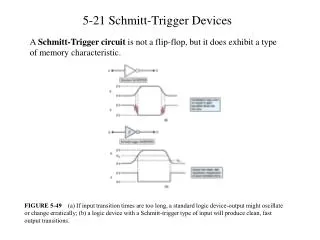
5-21 Schmitt-Trigger Devices A Schmitt-Trigger circuit is not a flip-flop, but it does exhibit a type of memory characteristic. FIGURE 5-49 (a) If input transition times are too long, a standard logic device-output might oscillate or change erratically; (b) a logic device with a Schmitt-trigger type of input will produce clean, fast output transitions.
5-22 One-shot (Monostable Multivibrator) One-short (OS) has only one stable output state . Once triggered, the outputs switch to the opposite state . It remains in this quasi-stable state for a fixed period of time tP. Two types: nonretriggerable and retriggerable FIGURE 5-50 OS symbol and typical waveforms for nonretriggerable operation.
5-22 One-shot cont. The retriggerable OS operates much like the the nonretriggerable one, except for one difference: it can be retriggered while it is in the quasi-stable state, and it will begin a new tP interval. FIGURE 5-51 (a) Comparison of nonretriggerable and retriggerable OS responses for tP = 2 ms. (b) Retriggerable OS begins a new tP interval each time it receives a trigger pulse.
5-22 One-shot cont. FIGURE 5-52 Logic symbols for the 74121 nonretriggerable one-shot; (a) traditional; (b) IEEE/ANSI.
5-23 Analyzing Sequential Circuit Example 5-16: All FF outputs are in the 0 state before the clock with 1kHZ are applied. Determine the waveforms at X, Y, Z and W. Solution: Step 1: Look for the familiar circuits such as counters, shift registers, and so on. Step 2: Write down the logic levels at the inputs and outputs prior to the occurrence of the first clock pulse. Step 3: Determine the new states of each FF in the response to the first clock pulse. Step 4: Repeat steps 2 and 3 for the following pulses.
5-24 Clock Generator Circuit Flip-flop: bistable multivibrator; One-shot: monostable multivibrator; An astable or free-running multivibrator switches between two unstable states and is used to generate clock. Examples are Schmitt-Trigger Oscillator, 555 Timer used as astable multivibrator and Crystal-Controlled clock Generators (which can satisfy the critical frequency accuracy and stability.) FIGURE 5-54 Schmitt-trigger oscillator using a 7414 INVERTER. A 8413 Schmitt-trigger NAND may also be used.
5-24 Clock Generator Circuit cont. FIGURE 5-55 555 timer IC used as an a stable multivibrator.
5-25 Troubleshooting Flip-flop Circuits Open Inputs FIGURE 5-56 Example 5-18.
5-25 Troubleshooting Flip-flop Circuits cont. • Consider the following possible faults: • Z2-5 is internally shorted to VCG . • Z1-4 is internally shorted to VCG . • Z2-5 or Z1-4 is externally shorted to VCG . • Z2-4 is internally or externally shorted to GROUND. This would keep Activated and would override the CLK input. • There is an internal failure in Z2 that prevents Q responding properly to its inputs. FIGURE 5-57 Example 5-19
5-25 Troubleshooting Flip-flop Circuits cont. Clock Skew FIGURE 5-58 Clock skew occurs when two flip-flops that are supposed to be clocked simultaneously are clocked at slightly different times due to a delay in the arrival of the clock signal at the second flip-flop.
Summary • With a memory characteristics, a flip-flop’s outputs will go to a new state in response to an input pulse and will remain in that new state after the input pulse is terminated. • A NAND latch and a NOR latch are simple FFs that respond to the logic levels on their SET and CLEAR inputs. • Clocked FFs are edge-triggered. • Most clocked FFs have asynchronous inputs that can set or clear the FF independently of the clock input. • Some of FF applications include data storage and transfer, data shifting ,counting, and frequency division. • One-short circuits, Schmitt-trigger circuits..