Download
1 / 48
480 likes | 627 Views
Development of SC Spoke Resonators at FNAL. G. Apollinari – Fermilab 4 th SPL Collaboration Meeting with ESS Lund, Sweden – July 1 st 2010. Project-X Evolution.

E N D
Development of SC Spoke Resonators at FNAL G. Apollinari– Fermilab 4th SPL Collaboration Meeting with ESS Lund, Sweden – July 1st 2010
Project-X Evolution • In the last year Project-X has evolved within the financial constraints of DOE to better meet the physics mission of US HEP community along 3 major lines of research: • Long baseline neutrino beam • High intensity, low energy protons for kaon and muon based precision experiments • A path toward a future muon facility – neutrino factory or muon collider • Initial Configuration 1 (IC-1) • 8 GeVLinac in MI, ILC paramters • Initial Configuration 2 – v1 • 2 GeV CW Linac + 2-8 GeV RCS • Initial Configuration 2 – v2 (IC-2v2) • 3 MW @ 3 GeV CW Linac CW nature requires SCRF acceleration from very low energies (2.5 MeV)
PrX – Beam Physics “Gospel” • The zero-current phase advances of transverse and longitudinal oscillations should be kept below 90° per focusing period to avoid instabilities at high current. • The wavenumbers of transverse and longitudinal particle oscillations must change adiabatically along the linac. This feature minimizes the potential for mismatches and helps to assure a current-independent lattice. • Minimize derivative of zero-current longitudinal phase advance along lattice, to reduce halo excitation. • Avoid the n=1 parametric resonance (zero current) between the transverse and longitudinal motion. • Avoid energy exchange between the transverse and longitudinal planes via space-charge resonances either by providing beam equi-partitioning or by avoiding instable areas in Hofmann’s stability charts . • Provide proper matching in the lattice transitions to avoid appreciable halo formation. • The length of the focusing period must be short, especially in the front end. • Beam matching between the cryostats: adjust parameters of outermost elements (solenoid fields, rf phase) See: P. Ostroumov talk, Feb.2, 2010, FNAL
Choice of Cavities • To be efficient at low-b • Low cryogenic losses • High (R/Q)G • High Gradient • Low Ep/Eacc and low Bp/Eacc • Large Velocity acceptance • Few accelerating gaps • Frequency Control • Low sensitivity to microphonics & low energy content http://www.lns.cornell.edu/public/SRF2005/talks/sunday/SuA04_talk_srf2005.pdf
Spoke Resonators 325 < f < 805MHz, 0.15 < b < 0.6 • Advantages • No dipole Steering • High performance • Lower Rsh than HWRs • Wide b range • Potential Problems • Not easy access • Difficult to tune • Larger size the HWRs • More expensive than HWRs • Quadrupole Steering
PrX - Initial Configuration 2 • For historical reasons(2005 Proton Driver) SSR(1) was the first SC low-b cavity developed at FNAL within the context of a pulsed 8 GeVLinac with SC cavities from 10 MeV. • CM segmentation, number of cavities/CM and the gap between CMs • 88 SSRs (325 MHz) • 138 Ellipt. (650 MHz) • 64 Ellipt. (1.3 GHz) (Initial) Performance Goals Freq (MHz) Bpk(mT) G (MV/m) Q @T (K) 325 60 15 1.4E10 2 650 72 16 1.7E10 2 1300 72 15 1.5E10 2
PrX – Initial Beam Elements Specs LB 650 SSR0 SSR1 LB 650 SSR0 SSR2 SSR1 SSR0 • Beam dynamics design completed and optimized for regular lattice, with break points and cavity types determined
Spoke Resonator Challenges • Design Optimization (SSR1) • Construction • (Feasibility of) Assembly • Engineering Safety • Operations • Gradient and Q0 performance • Tunability • Lorentz Force Detuning (Pulsed) and Microphonics (CW) • High Power Operations • Cryomodule Integration and Test Facility • (Beamline) Integration • Focusing Elements • Instrumentation • Cryomodule Assembly & Commissioning • Meson Detector Building Test Facility
RF Design optimization Mechanical analysis and optimization L SSR1 Design Optimization V Total Deformation at 2 atm. • Built 2 prototypes + 2 additional from IUAC (India).
Assembly Model Vacuum port Bridge ribs Shell End wall Beam port spoke Daisy ribs Donut rib Coupler port
Spoke Assembly Spoke Forming Collar Forming Spoke Welding
“Stiffening” Ribs Caveat: Ribs designed for Pulsed Operation Stiffening
Brazed Ports for He Vessel Vacuum port Bridge ribs Shell • Brazing Process • Initially developed at CERN (1987) later modified at ANL (2003) • Filler metal: CDA-101 high purity copper wire • SST flanges pre-machined, stress relieved at 1100 C and finished • Yield limit 6700 lbs • Allows assembly of SS He-Vessel End wall Beam port T Braze spike soak Cool down Ramp up vent spoke t Coupler port Donut rib Daisy ribs
Cavity Tuning BCP at ANL
Helium Vessel Assembly Bellow and End-plate welding process 3-D Model
SSR Tuner Stepper Motor & Harmonics Drive Slow Tuner Arm “ Safety Rod” attached cavity flange to slow tuner arm
Engineering Note & Safety • “ASME Boiler and Pressure Vessel” code (US) introduced in 1905 to address exploding boilers (before then, individual state regulations). • Dp > 15 psi (~1 atm.) & Dimension > 6 in (15 cm) • EU has “Pressure Equipment Directive” (PED) since ~2005, individual countries regulations before then • Dp > 0.5 atm & Volume > 1 L • SCRF assemblies cannot meet fully the requirements of the US-ASME code (ex: Nb is not a code-allowed material) • (Possible) strategies: • Director’s “magic wand” for exceptional vessel approval • SNS/JLAB approach: coded cryomodule vacuum vessels as pressure containment • Develop standards such that necessary deviation from code (Nb) are handled by special procedures (measuring the mechanical properties of samples of the niobium from the lot of material from which the cavities are made)
Engineering Analysis • Present Strategy: • Minimize number of “exceptions” to code • Use of Nb (not explicitely allowed by the code) • No ultrasonic examination of EB welding along entire length • Lack of WPS (Weld Procedure Specs) PQR (Procedure Qualification Records) and WPQ (Welder Performance Qualification) for Nb and SS assemblies • Nb-SS brazing did not have a Brazing Procedure Specification • Demonstrate safety by engineering analysis and pressure testing
Spokes Cavity Vertical Test • SSR1-1 • Four VTS tests between March 2008 and March 2009 • Vacuum problems in first two tests • Active pumping added to VTS before 4th test • 4th test included cool-down dwell at 100° K in attempt to induce Q-disease • Will next be tested in new test cryostat in coming months • SSR1-2 • One VTS test in 2009 • Reached gradient – 33MV/m • Eacc=Acc. Voltage/Liris =Acc. Voltage/2/3 bl
SSR1-2 First VTS Test 60 mT
PC High Power Test Fixture • Three Fermilab-designed couplers produced and in house • Average power of 4.2 kW (2 Hz, 3 ms, 700 kW) was sustained for 2 hours, and an additional 3 hour test at 3.3 kW (2 Hz, 3 ms, 550 kW) was performed.
High Power Test • Horizontal Test Cryostat for High Power (~250 kW) SSR testing
Spoke Resonator Challenges • Design Optimization (SSR1) • Construction • (Feasibility of) Assembly • Engineering Safety • Operations • Gradient and Q0 performance • Tunability • Lorentz Force Detuning (Pulsed) and Microphonics (CW) ~ High Power Operations • Cryomodule Integration and Test Facility • (Beamline) Integration • Focusing Elements • Instrumentation • Cryomodule Assembly & Commissioning • Meson Detector Building Test Facility
SSR1 Cryomodule Model • Present concept of SSR1 Cryomodules • Contain 9 SSR1 cavities and 9 solenoids • Project X expects that these designs could be extended to SSR0 and SSR2 requirements
Cryomodule Assembly • Assembly performed using the same or similar tooling to that used for 1.3 GHz (XFEL/ILC) final assembly • Also studying the advantages/disadvantages of “bath-tub” assembly
SSR0 RF Design Optimization blue red Eacc*=Eacc(βoptimal)* TTF, Average green E Field B Field
SSR0 Mechanical Optimization Displacement 0.1 mm Force reaction 315 x 4 K = 315*4/0.1 = 12600 N/mm ~ 13 N/µm
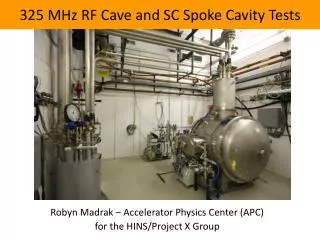
Meson Detector Building Setup • MDB/HINS initially (2005) conceived as development ground for 325 MHz Front End for the initial Project X configuration (8 GeV Pulsed Linac, SC from 10 MeV) • Initial Goals: • Testing ground/conditioning for all 325 MHz equipment • Accelerate beam from 0 to ~60 MeV through RFQ, MEBT, RT section (2.5-10 MeV) and SC SSR1 section (10-60 MeV) • Control RF power to cavities • Beam Chopper Development • Beam Instrumentation Development • Revised Goals: • In CW design, RT section eliminated. Probably replaced by “short” SSR0 cryomodule (~3 cavities) for “proof of principle” acceleration with SSRs • Testing ground for MEBT section, chopper and beam diagnostic
Layout for 3-Cavity SSR0 Cryostat 18° spectrometer ~2.7 m length actual HINS absorber/shielding 10 m MEBT/CHOPPER 13.4 m Existing ion source and RFQ 0 m 10.5 m 16.9 m 14.2 m 10.5 foot ceiling 0.5 m end 0.5 m end 2.4 m cryostat
First 2.5 MeV Beam through RFQ Signals from toroid and two BPM buttons, all downstream of the RFQ Upper display: 2 μsec/div Lower display: 20 nsec/div Lower display shows the 44nsec delay expected for transit of 2.5 MeV beam between the BPM two buttons separated by 0.96 meters Beam current is about 3 mA
Conclusions • Project X has adopted Superconducting Spoke Resonators for the Front End • Design and development of bare cavities is by now a “routine” operation • Valuable experience is being gained in the assembly and operation of “dressed” cavities. • Design of the SSR cryomodule is still in its early stages.
Quarter Wave Resonator 40 < f < 160 MHz, 0.001 < b < 0.2 • Advantages • Compact • Modular • High performance • Low Cost • Low Beta • Potential Problems • Field asymmetry (to be compensated by dipole steering or gap shaping) • Mechanical Stability OPERATING
Half-Wave Resonator 160 < f < 350MHz, 0.09 < b < 0.3 • Advantages • No dipole Steering • High performance • Lower Ep than QWR • Wide b range • Very compact • Potential Problems • Not easy access • Difficult to tune • Less efficient than QWRs
PrX – Beam Physics “Gospel” (cont.) • Provide proper matching in the lattice transitions to avoid appreciable halo formation. In the perfect “current-independent” design, matching in the transitions is provided automatically if the beam emittance does not grow for higher currents. • Stability for zero current beam, defocusing factor should be < 0.7. (Defocusing factor is less for lower frequencies for given Em) • The length of the focusing period must be short, especially in the front end. • Beam matching between the cryostats: adjust parameters of outermost elements (solenoid fields, rf phase) • In the frequency transition, the longitudinal matching is provided by 90° “bunch rotation”, or bunch compression
SSR1-1 Early VTS Results • SSR1-1 Q vs. E • Dressed Cavity Operating Goal @ 4 K (Pulsed) • This test ended when multipacting due to poor cavity vacuum became unacceptable. O • Accelerating Gradient MV/m
“Complete” Layout Existing RF1-3900P80 and RF2-1300P300 Existing RF9-325CW0.4 NEW RF3-1300CW30 and RF6-650CW30 HTS-2 Existing RF8-325P2500 325 CAGE NEW RF11-325CW1.5 Caveats: Physical Sizes of RF4-1300P1000, RF7-650P100 and RF10-325CW30 are not known Layout does not show RF5-1300P100. It is assumed that RF2-1300P250 or RF4-1300P1000 serves that purpose. Relocated 325 MHz RF Component Test Facility NEW RF4-1300P1000 and RF7-650P100 NEW RF10-325CW30
Goals • Complete “Six-Cavity Test” – June 2011 • Demonstrate individual Phase/Amplitude control with DQM shifters. • Demonstrate that solenoid beam axis can be aligned to 0.5 mm rms – by Oct 2011 • Select bunch frequency (162.5 or 325) by demonstrating a broad-band chopper – by July 2013 (CD2) • Complete test of SSR0 “short” cryomodule (3/4 cavities, 4/5 solenoids + correctors, BPMs) (prototype for a “long” cryomodule) with beam and broad-band chopper – by Sept 2014 • Ongoing development of instrumentation, optics, couplers, LLRF
Ion Source Emittance Scan Data Horizontal 50 keV beam from HINS proton ion source Vertical Ib = 4 mA Ib = 12 mA
RFQ Problem & its solution Note RF joint seal RF joint seal buckled