Download
1 / 40
440 likes | 662 Views
Strain-enhanced Device and Circuit for Optical Communication System. 指導教授:劉致為 博士 學生:余名薪 台灣大學電子工程學研究所. Outline. Introduction Optical Communication System Mechanical/Package Strain Technique Strain-enhanced MOS Photodetector Strain-enhanced Transimpedance Amplifier

E N D
Strain-enhanced Device and Circuit forOptical Communication System 指導教授:劉致為 博士 學生:余名薪 台灣大學電子工程學研究所
Outline • Introduction • Optical Communication System • Mechanical/Package Strain Technique • Strain-enhanced MOS Photodetector • Strain-enhanced Transimpedance Amplifier • 7Gb/s Transimpedance Amplifier • SiGe HBT BiCMOS Active Inductor • Summary and Future Work
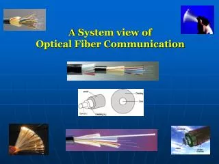
Optical Communication System System block diagram Transmitter Medium Receiver Photodetector & Transimpedance Amplifier (TIA)
Mechanical/Package Strain Technique Mechanical setup (detector) Biaxial Tensile Strain Uniaxial Tensile Strain Side view Top view
Mechanical/Package Strain Technique Mechanical setup (circuit chip) Biaxial Tensile Strain Uniaxial Tensile Strain
Mechanical/Package Strain Technique Ramam & Electroluminescence spectra • The red-shift of Si-Si peak in Ramam spectra indicates 0.13% biaxial tensile strain • and 0.35% uniaxial tensile strain. • The EL spectra of a MOS LED under tensile strain indicates bandgap shrinkage. Ramam spectrum EL spectrum
Mechanical/Package Strain Technique Current enhancement in MOSFET • The drain current is enhanced owing to the electron mobility enhancement. • NFET has enhancement under tensile strain, and PFET has enhancement • under uniaxial compressive strain parallel to channel and the uniaxial tensile • strain perpendicular to channel.
Outline • Introduction • Strain-enhanced MOS Photodetector • Metal/Thin-oxide/P-Si Tunneling Diode Photodetector • Responsivity Enhancement by Tensile Strain • Strain-enhanced Transimpedance Amplifier • 7Gb/s Transimpedance Amplifier • SiGe HBTBiCMOS Active Inductor • Summary and Future Work
MOS Tunneling Diode Photodetector I-V & C-V characteristics • At the negative bias region, the device can serve as a LED. When the gate is biased at the positive voltage greater than threshold voltage, the device can serve as a PD. • C-V indicates that the deep depletion in the NMOS tunneling diode is formed for the large positive gate bias. I-V curve C-V curve
MOS Tunneling Diode Photodetector Band diagram • The bandgap shrinkage enlarges the concentration of the electron in the bulk • silicon, and since the tunneling process would not be the limiting factor for • electron to go from p-Si to Al gate, the photo current increases. Namely, the • responsivity is enhanced. Accumulation (LED) Inversion (Detector)
MOS Tunneling Diode Photodetector Measurement • The dark current has almost no change under strain, and the photo current • is enhanced gradually with increasing strain. Biaxial tensile strain Uniaxial tensile strain
MOS Tunneling Diode Photodetector Responsivity enhancement • Uniaxial strain has potentiality to achieve higher strain gauge than biaxial strain. • The maximum of current enhancement is about 12% and 14% under biaxial and • uniaxial strain respectively. 14% 12%
Outline • Introduction • Strain-enhanced MOS Photodetector • Strain-enhanced Transimpedance Amplifier • Circuit Design & Simulation • Bandwidth Enhancement by Tensile Strain • 7Gb/s Transimpedance Amplifier • SiGe HBT BiCMOS Active Inductor • Summary and Future Work
Strain-enhanced Transimpedance Amplifier Circuit schematic Main Gain Stage Peaking Stage
Strain-enhanced Transimpedance Amplifier Inductive peaking • For m = 0.4, the transfer function exhibits a maximum flat response with a • bandwidth improvement of 70% compared to a simple common source • amplifier. If m = 0.7, the bandwidth reaches its maximum value with 1.5dB • peaking and 85% improvement. (τ= RC , m = L/R2C ) Active Inductor
Strain-enhanced Transimpedance Amplifier Bandwidth enhancement Active Inductor : Peaking Stage : After strain After strain
Strain-enhanced Transimpedance Amplifier Frequency response & Stability Magnitude response Phase response Gain: 60dBΩ Bandwidth: 3.5GHz Peaking < 0.5dB K factor Δ factor Δ< 1 K > 1
Strain-enhanced Transimpedance Amplifier Input-referred noise current density & Eye diagram Input-referred noise current density Jitter < 20ps Eye Diagram at 3.125Gb/s, 20uA
Strain-enhanced Transimpedance Amplifier Performance Summary
Strain-enhanced Transimpedance Amplifier Measurement : Bandwidth enhancement • Through 0.06% biaxial tensile strain, the characteristic of active inductor can • be modified, thus improves the -3dB frequency. • The bandwidth enhancement is about 5.5%.
Strain-enhanced Transimpedance Amplifier Circuit layout & Die photograph Layout Die photo
Outline • Introduction • Strain-enhanced MOS Photodetector • Strain-enhanced Transimpedance Amplifier • 7Gb/s Transimpedance Amplifier • Circuit Design & Simulation • Measurement • SiGe HBT BiCMOS Active Inductor • Summary and Future Work
7Gb/s Transimpedance Amplifier Circuit schematic
7Gb/s Transimpedance Amplifier Frequency response & Stability Magnitude response Phase response Gain: 56dBΩ Bandwidth: 8GHz Peaking < 1dB K factor Δ factor Δ< 1 K > 1
7Gb/s Transimpedance Amplifier Input-referred noise current density & Eye diagram Input-referred noise current density Jitter < 15ps Eye Diagram at 10Gb/s, 20uA
7Gb/s Transimpedance Amplifier Measurement : S-parameters S11 S12 S21 S22
7Gb/s Transimpedance Amplifier Measurement : Frequency response Transform function: Gain: 57dBΩ Bandwidth: 6GHz Magnitude response Phase response
7Gb/s Transimpedance Amplifier Measurement : Eye diagram 2.5 Gb/s PRBS 3.125 Gb/s PRBS • Measured on PCB. • Equivalent input current ~ 50uA. • Eye can open well under 7Gb/s PRBS. • Jitter < 35ps @ 7Gb/s • The inductive characteristic of bond wire • may help improve overall bandwidth. 7 Gb/s PRBS
7Gb/s Transimpedance Amplifier Performance Summary
7Gb/s Transimpedance Amplifier Die & PCB photograph PCB photo Die photo PCB layout
Outline • Introduction • Strain-enhanced MOS Photodetector • Strain-enhanced Transimpedance Amplifier • 7Gb/s Transimpedance Amplifier • SiGe HBTBiCMOS Active Inductor • CMOS Active Inductor • BiCMOS Active Inductor • Summary and Future Work
SiGe HBT BiCMOS Active Inductor Basic configuration of active inductor Gyrator-C topology: Two-transistor active inductor: CS-CD type CS-CG type
SiGe HBT BiCMOS Active Inductor Proposed active inductor Equivalent model : Cascode BiCMOS Type A
SiGe HBT BiCMOS Active Inductor Zin analysis Zin
SiGe HBT BiCMOS Active Inductor Frequency response of input impedance • For fair comparison, all the active inductors are designed with identical MOSFET size • and power consumption. • BiCMOS active inductor has wider inductive range. • The phase of BiCMOS type rises at lower frequency and reaches the higher degree, • which means BiCMOS type has much higher quality factor and less resistive loss. Magnitude Phase
SiGe HBT BiCMOS Active Inductor Inductance & Quality factor • BiCMOS type has much higher resonant frequency. • Cascode will reduce the resonant frequency owing to its extra parasitics, but it • provides higher inductance at high frequency and higher quality factor. Inductance Q-factor
SiGe HBT BiCMOS Active Inductor Inductor characteristic tuning I1 increasing I1 tuning I1 increasing I2 tuning I2 increasing I2 increasing VB tuning VB increasing VB increasing Inductance Q-factor
Outline • Introduction • Strain-enhanced MOS Photodetector • Strain-enhanced Transimpedance Amplifier • 7Gb/s Transimpedance Amplifier • SiGe HBT BiCMOS Active Inductor • Summary and Future Work • Summary • CMOS Image Sensor
Summary • A novel metal/thin-oxide/silicon structure tunneling diode photo detector is proposed. With biaxial or uniaxial tensile strain, the band-gap of bulk Si shrinks, resulting in higher electron concentration under identical exposure, thus the responsivity is enhanced. The maximum of responsivity enhancement under biaxial and uniaxial tensile strain are about 12% and 14% respectively. • A Transimpedance Amplifier (TIA) adopting active inductor is designed. Through inductive characteristic tuning by biaxial tensile strain, a 5.5% bandwidth enhancement can be achieved. • A 7Gb/s transimpedance amplifier fabricated with TSMC 0.18um CMOS process is proposed. The measured gain and bandwidth are 57dBΩ and 6GHz respectively. The eye can open well with operation under 7Gb/s PRBS. • A novel BiCMOS type active inductor is proposed. From simulation, it can be proved that BiCMOS active inductor can achieve higher quality factor and resonant frequency than CMOS type with the great help from SiGe HBT. However, the inductance value would be slightly lower.
Future Work CMOS image sensor • The photodiode can be replaced with our MOS tunneling diode photodetector by connecting the gate of the diode to the source of transfer gate. • The lower dark current(~3nA/cm2) and higher • quantum efficiency (~80%) can improve the • performance of the pixel, such as dynamic range • and sensitivity. Replace with MOS detector