Download
1 / 21
210 likes | 322 Views
Polyurethane Cuff Dipping Machine Design Review. Todd Clark Noah Hopson Jason Johnson Chris Knowlton Kris Koster Mike Schierbeek. Overview. Design a fixture/machine that can: Manufacture polyurethane cuffs to a predetermined thickness using pre-existing mandrels for the cuffs.

E N D
Polyurethane Cuff Dipping Machine Design Review Todd Clark Noah Hopson Jason Johnson Chris Knowlton Kris Koster Mike Schierbeek
Overview • Design a fixture/machine that can: • Manufacture polyurethane cuffs to a predetermined thickness using pre-existing mandrels for the cuffs. • Measure the viscosity of the polyurethane solution • Reduce or eliminate bubbles that appear in the solution.
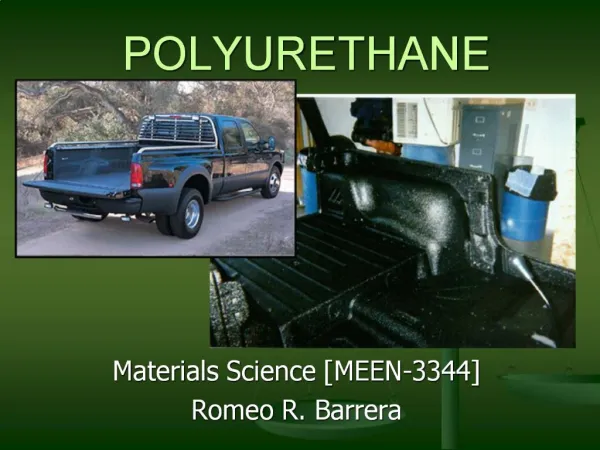
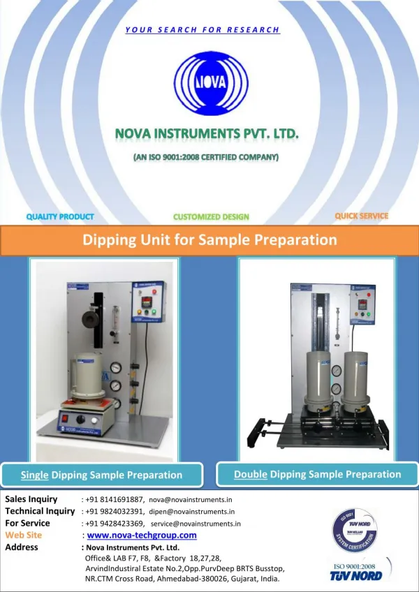
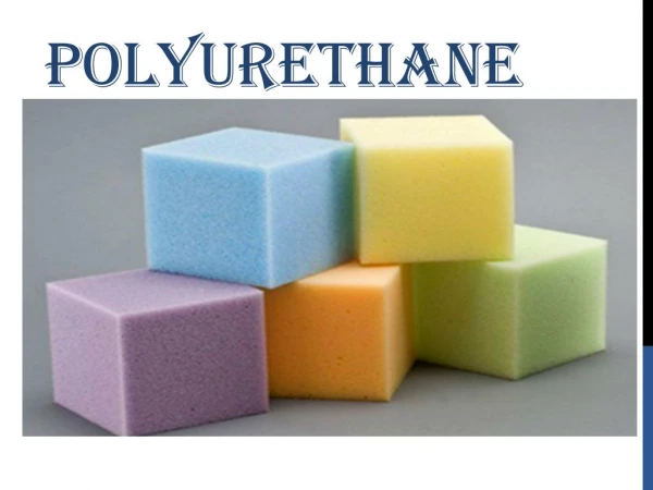
Process Overview • Polyurethane solution is created by dissolving polyurethane pellets in a solvent • A stainless steel mandrel is then dipped into the polyurethane solution • The solvent flashes from mandrel, leaving only the polyurethane • This polyurethane is left as a thin layer over the mandrel
Objectives • Design a polyurethane cuff dipping machine capable of: • Producing quality cuffs • Reduce bubbles in the dip solution • Ensuring a fully mixed dip solution • Using a smooth dipping profile • Accepting multiple part programs • Monitor process parameters • Active viscosity control • Ambient temperature and humidity
Constraints • Budget of $25,000 • Use a dipping system that will eliminate sparking • No brushed DC motors • Use materials that are compatible with Tetrahydrofuran (THF) • Clean room compatible
Specifications • Dipping • Must be able to dip two 15 in. mandrel bars • Minimum velocity of 0.04 in/sec • Store 1 gal. of THF solvent for viscosity adjustment • Store 2 gal. of premixed polyurethane for dip tank level adjustment • Fits through a standard 32 inch door • Store multiple part programs • Operating and maintenance access should be on one side
Scope of Work • Research • Polyurethane dipping process • Polyurethane solution mixing • Design • Size components • Determine component placement with overall ergonomics in mind • Construction • Assemble frame • Place components • Wire machine • Testing/Calibration • Programming • Test program • Calibrate viscometer
Frame • MayTec aluminum extrusion • Durable and sturdy machine platform • All components contained within the frame
Linear Actuator • Stepper motor driven • Easily controlled • Accurate positioning • Ball screw linear system • Smooth motion profile • Accurate positioning • Long operating life • Speed range of 0.04 in/sec to 0.8 in/sec
Two pneumatic rotary actuators 40 in lbs of torque at 80 psi (each) Smooth rotation Adjustable speed Based on air flow Rotation along the long axis of the mandrel bar Uniform velocity for all mandrels Eliminates solution ‘creep’ due to excessive movement Mandrel Bar Rotator
Dip Tank • Stainless steel construction • Accepts (2) ten mandrel bars • Level is monitored by a capacitive proximity sensor • Incorporates: • Viscometer • Solution/Solvent fittings • Drain • Magnetic Stir Bars
Viscometer • Cambridge Viscosity viscometer • Inline process model • Adapted for in tank operation • 2.5-50 Cps sampling range • Continuous viscosity sampling • 4-20 mA analog output for viscosity adjustment
Dip Tank Lid • Seal eliminates unwanted solvent evaporation • Eliminates solution contamination • Dual pneumatic cylinders operate lid system • Guides move lid off and behind tank for dipping
Mixing System • Based on proven laboratory stir plate technology • Three stir bar magnetic couplers • Belt driven system • AC induction motor controlled by VFD
Reservoir System • Tanks are stainless steel pressure vessels • Fluid level is monitored by capacitive proximity sensor • Solution and solvent transferred to the dip tank via stainless steel braided PTFE hose • Flow controlled by needle valve and PLC controlled solenoid • Tanks are attached to a drawer to make changing easier
Guard System • Dipping door is operated by two pneumatic air cylinders • Controlled by palm buttons via PLC • Safety bumper switch prevents operator from being pinched
Allows user to change process parameters Allows manual operation of system components Displays process parameters to the operator Displays machine status HMI Controller
Overall System • Compact Size • 30” wide x 40” deep x 68” tall • Meets required specifications • Safe and ergonomic design • Maintenance oriented • Fully adjustable dipping process
Budget • Project budget of $25,000 • Estimated completion cost of $23,500
Schedule • Begin Ordering Parts – April 30th • Begin Construction – May 5th • Begin Programming – May 12th • Finish Construction – June 10th • Finish Programming – June 23rd • Testing and De-bugging through July 7th