Download
1 / 16
180 likes | 442 Views
GBM Simulation and Instrument Response. R. Marc Kippen Space and Atmospheric Sciences Group Los Alamos National Laboratory. GRB. GBM Detector / Instrument Response. Observed Data. GRB Photon Spectrum. Instrument Response. Instrument Background. Simulation and Detector Response Software.

E N D
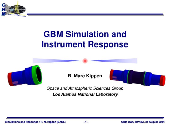
GBM Simulation and Instrument Response R. Marc Kippen Space and Atmospheric Sciences Group Los Alamos National Laboratory
GRB GBM Detector / Instrument Response Observed Data GRB Photon Spectrum Instrument Response Instrument Background
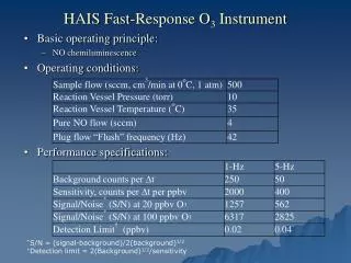
Simulation and Detector Response Software • Definition: Multi-purpose software suite that computes the physical and instrumental response of the GBM instrument system • Primary purpose: generate detector response functions critical to the analysis of flight science data • Other uses: instrument design; interpretation of calibrations; design of flight and ground analysis algorithms & s/w • Technique: Numerical simulation — Monte Carlo radiation transport • Verified through, and incorporating results from experimental calibration Major Components • Mass model (geometry + composition) • Incident particle distributions • Radiation transport physics • Instrumental/calibration effects • DRM database • DRM synthesizer/generator
Key Functional Specifications GBM SIM/DRM S/W Functional Specs GBM-SPEC-1025 (reviewed at GSW PDR) GBM IODA S/W Functional Specs GBM-SPEC-1031 (reviewed at GSW PDR) • Complete and accurate interaction physics (included in core simulation package — GEANT4) • Accurate mass models, environment models, and instrument models (but not overly complex) • Later stages of development require S/C models (including LAT model) • Verification through comparison with experimental data • Final DRMs must include contribution from atmospheric scattering (+direct detector and S/C scattered response) • GLAST S/C will have rapid slew capability — different DRMs are required whenever aspect changes by > 1° • DRM generation s/w is part of GBM IODA s/w and subject to the same requirements for standards, configuration control, etc.
SIM/DRM software designed and developed at LANL in collaboration with GBM PI and GSW lead Development process falls under GSW Development Plan (GBM-PLAN-1023) Final products (s/w and data) delivered to GBM PI at NSSTC (also available to MPE and other interested parties) GBM Principal Investigator (Meegan) GBM Project Manager (Elrod) Ground System Manager (Paciesas) Ground Software Lead (Preece) SIM & DRM System Lead (Kippen) Developers (Hoover) Ground Software Review Board GSW Config. Mgr. (Connaughton) Ground Software Test Team (Diehl, lead) Ground Software Development Team Development Organization
Software and models require cross-validation with calibration data Three phases of SIM/DRM sw/model development Design Simulate prototype detectors Calibration Simulate three levels of calibration/test Detector level GBM system level On-spacecraft level Operation In-flight configuration appropriate for analysis of science data DRM generation Environment Models Instrumental Effects Mass Models Design Phase Prototype Detectors Prototype Environment Prototype Thresholds, Resolution Flight Detectors, Det. Level Config. Test Environment 1 Detector Level Env. Test Environment 1 Det. Cal. Results Flight Detectors, Sys. Level Config Test Environment 2 System Level Env. Test Environment 2 Sys. Cal. Results Calibration Phase Flight Detectors, SC Level Config. with Spacecraft/LAT in Test Configuration Test Environment 3 Spacecraft Test Facility and Source Holder Test Environment 3 S/C Cal. Results Flight Detectors, Flight Configuration with Spacecraft/LAT in Flight Configuration Flight Environment with Atmospheric Scattering Model Flight Performance with Periodic Updates from In-flight Calibration Database Operations Phase Phased Software/Model Development
Integrated package that will encompass all GBM instrument response software and data needs Configuration controlled as a single deliverable package with component software/data modules All packages (and their dependencies) use GNU compilers — mainly g++ All data files have headers with detailed version & job tracking data Final phase package will be a subset of the GBM IODA software, cf. GBM-SPEC-1036 (GSW Arch. Design) Implementation:GBM REsponse Simulation System GRESS gbmsim GBM instrument physical simulator calsim Instrumental/calibration effects & data packager atmosim Atmospheric scattering simulator arpack Atmospheric scattering data packager drmgen Application-specific DRM generator
Implementation:GBM REsponse Simulation System GRESS/IODA Overlap Area GRESS IODA Cal. Params. Cmds. Mass model Data Analysis Software (IOC) drmdb root files gbmsim calsim Cmds. drmgen Aux. data Application Specific DRM Spectrum or DRM caldb atmosim armdb root files arpack Source Location Software (SSC & IOC) Cmds. Mass model Spectrum or ARM Note: a separate, reduced DRM/ARM database is used for BAP software (based on same simulation data)
How – Direct Instrument Response gbmsim — Raw “physical” data calsim — Packaged, instrument-like data
collection surface How – Atmospheric Scattered Response atmosim — Raw “physical” data arpack — Packaged data matrix NRLMSISE-2000 atmospheric model used to create concentric shell mass model
drmdb — direct response db armdb – Atmos. Resp. db How — Putting it all Together drmgen — burst-specific response generator Data Analysis – spectral fitting and localization
Parameterized spectral models Built-in models or “custom” models How — Response used for Spectral Analysis rmfit/xspec — spectral model “hypothesis testing” Observed/Predicted Counts Model GRB Spectrum Total Det. Response Background Model iterate • From drmgen • Updated automatically when S/C pointing changes • Empirical, time-dependent model based on data before and after burst • Observed and predicted counts compared via test statistic • Chi-squared (Gaussian) or Poisson log Likelihood • Optimize test Stat. iteratively Process is extended to simultaneously include multiple GBM detectors (Incl. NaI and BGO) or other instruments (e.g., LAT, Swift, etc.)
Trial GRB Direction How — Response used for Localization Simultaneous spatial/spectral model “hypothesis testing” Internal response generator Predicted detector counts Chi-square evaluation Trial Spectral Parameters Observed Det. counts Spatial/spectral optimization S/C attitude/ position Background model caldb
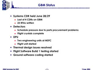
Development Status • SIM/DRM development is affected by: • Delivery of GBM detector design data/drawings (received June 2004, three months behind original schedule) • Delivery of GLAST spacecraft design data/drawings (expected July 2004, three months behind original schedule, initial delivery August 2004) • Schedule of GBM calibrations • Required to verify SIM/DRM s/w and models • Detector level (MPE), system level (NSSTC), spacecraft level (Spectrum) — all slipped due to launch slip. • Development status: • Preliminary versions of GRESS software complete (several months ahead of schedule) • Detector model development nearing completion (3 months behind) • Spacecraft model development starting (3 months behind) • Result: able to meet required delivery schedule
SIM/DRM Revised Delivery Schedule Stable since GBM System CDR June 2004 • * All deliveries from LANL to NSSTC • † Schedule changes from ground s/w CDR reflect changes in • the GBM calibration schedule (affected by launch slip)